Archive for the ‘Elevators’ Category

Re-attached empennage

Sunday, April 26th, 2020

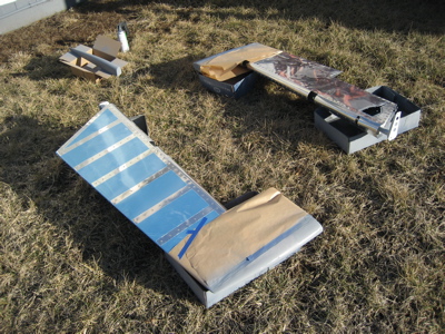
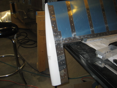
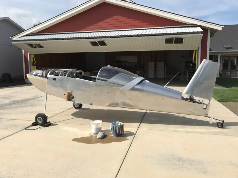
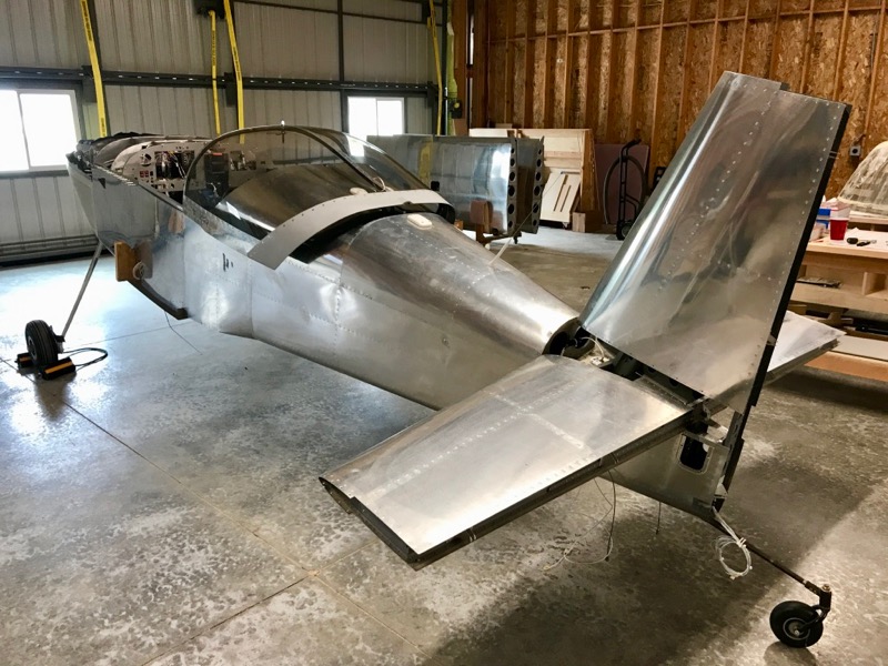
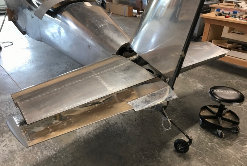
Finally, some work on the airplane! First of all, after being hauled halfway across the country and then sitting in a series of dusty locations for over four years, the fuselage was absolutely filthy. Before trying to work on anything I dragged it outside and gave it a sponge bath:

Then I removed the jury-rigged arrangement of wood blocks and clamps that had been holding the vertical stabilizer in place, installed the horizontal stabilizer again, and torqued all the HS and VS mounting bolts.

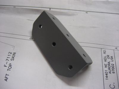
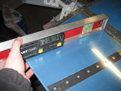
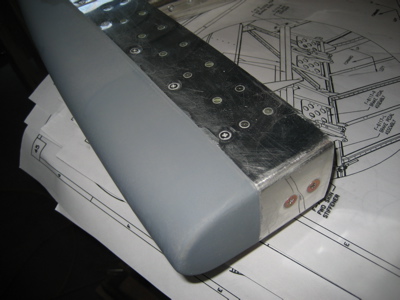
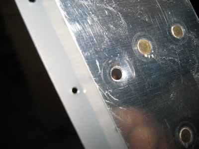
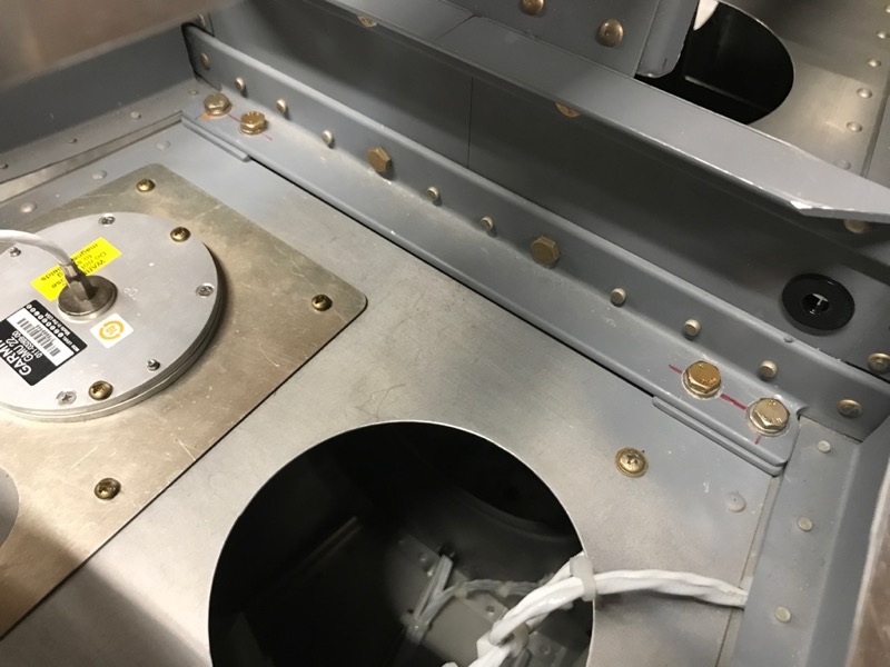
Getting access to all these fasteners to install and torque them properly is a real wrist-shredding exercise. Here's photo proof that I remembered to reinstall the F-798 shims under the leading edge of the horizontal stabilizer:

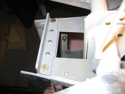
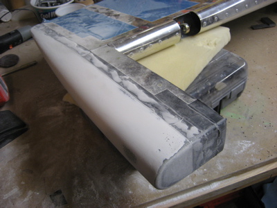
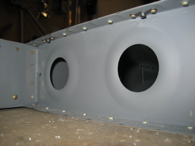
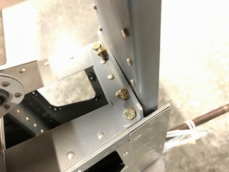
And, the single washer/spacer between the vertical stabilizer spar and the elevator stop on the left side only:

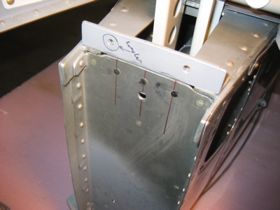
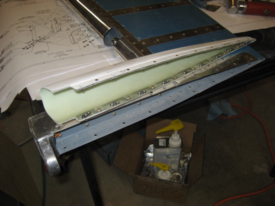
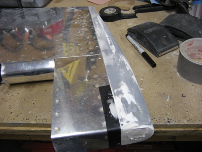
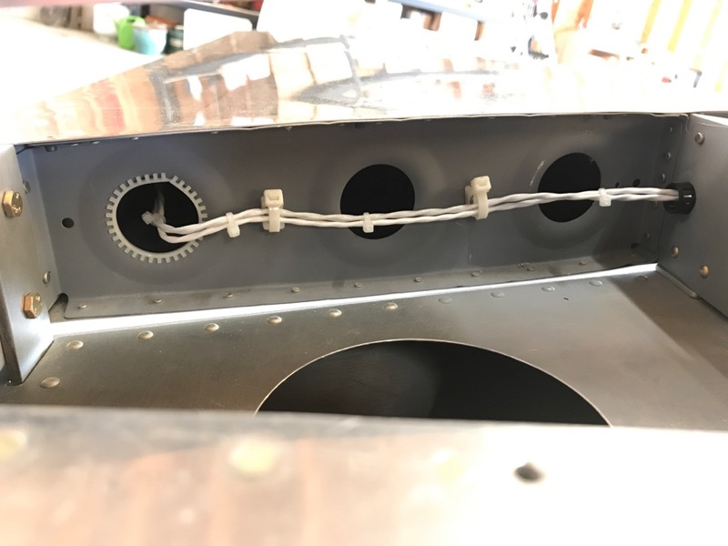
Since I never previously had room to leave the elevators attached permanently, I hadn't yet finished routing the wires to the left elevator for the trim tab motor and position sensor. Now I've tie-wrapped them to the left-side root rib of the horizontal stabilizer, and run them back to the elevator through the previously-drilled bushing hole. I added some nylon grommet edge material to the lightening hole too, which is probably not necessary but makes me feel better.

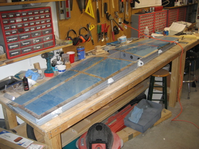
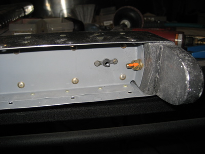
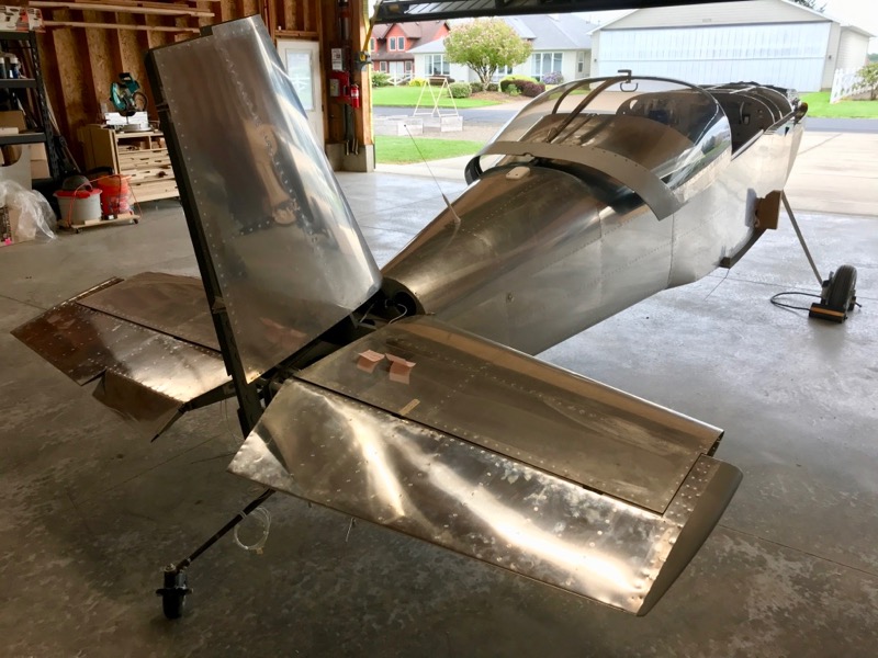
Here's the left elevator installed with the correct bolts and everything torqued:

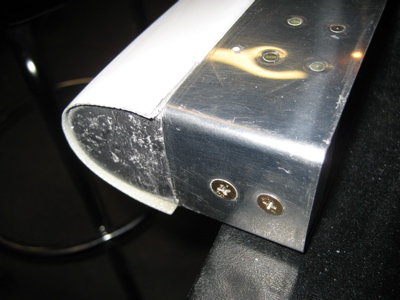
And here's the right elevator installed too. Believe it or not, it took a solid day of work to get to this point from the last photo. Properly installing the elevator pivot bolts and spacer washers is a real exercise in frustration, and you have to take your time and take great pains to get everything exactly aligned or else you'll wind up with unwanted control friction. I must have had the elevators on and off the airplane at least fifty times adjusting various things, but the result is a set of elevators that moves with very little drag.

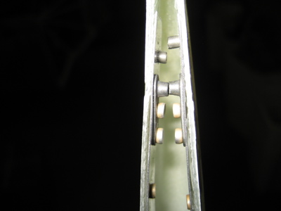
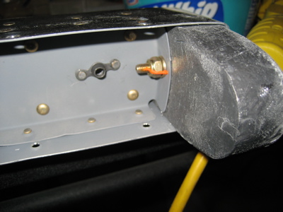
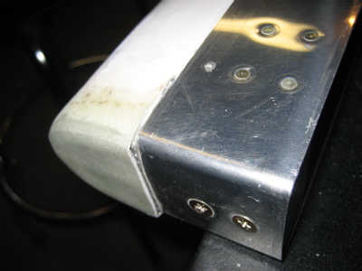
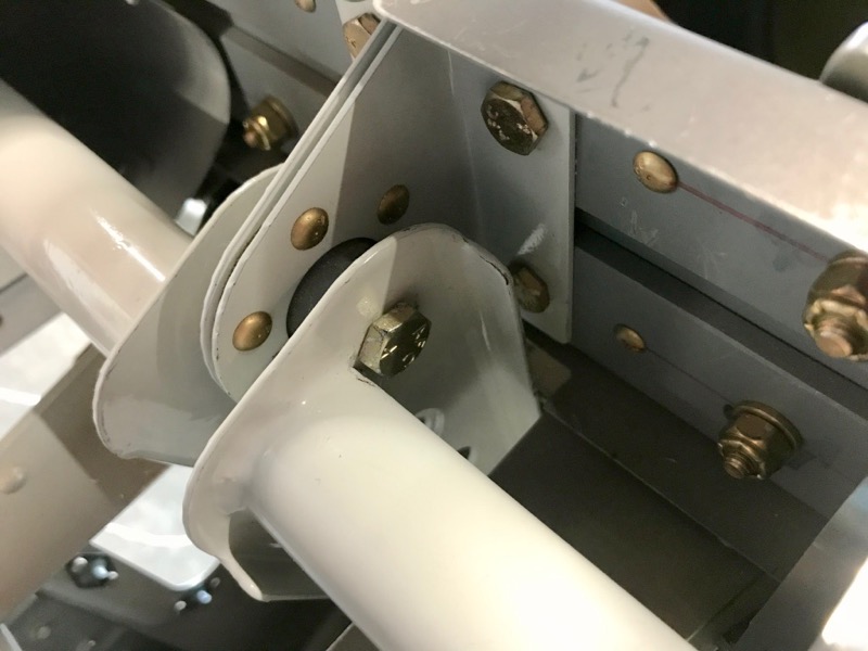
I ran into a trap I unknowingly set for myself years ago… the hole I drilled for the center elevator pivot bolt is awfully close to the torque tube, which means getting a wrench on the bolt head is almost impossible. I ended up making it work with a crow's foot wrench, but it was a close-run thing. In retrospect the plans set you up to fail here, because there's no warning about this possibility, and it's very easy to have this happen if you blindly follow the prescribed dimensions for installing the rod end bearings.

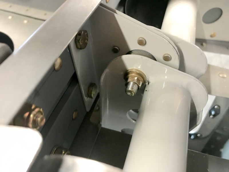
The other side was just as bad – I ended up using a MS21042 metal locknut here in place of the specified AN365, because I was able to get a socket on its smaller-diameter head. Still, it was a real fight, requiring all manner of adapters and flex couplings to make it work. I'm not worried about this fastener substitution, since the specs say you can directly substitute a MS21042 for the equivalent nyloc nut.

The plans are silent on the specifics of how to properly install the elevators, so here are some notes based on my experience:

1. If you haven't drilled the holes for the center pivot bolt yet, make sure you don't place it too close to the torque tube (or the flange, which would be just as bad).

2. Use temporary hardware when fitting the elevators, since you will have them on and off a lot. Plain nuts nuts in place of locknuts will save you a lot of time and effort. Use the proper hardware for the very final installation, obviously.

3. First install one elevator only. Insert the center pivot bolt, but don't worry about the spacers between the control horn and center bearing yet. With the center bolt in place, you want the elevator to be light as a feather, with essentially no resistance. If it binds or drags at this point, you have an alignment problem and you need to adjust one or both rod end bearings. Repeat until the elevator pivots freely.

4. Tighten the nuts on the middle and outer pivot bolts and check for freedom of movement. If the elevator was friction-free after step #3 but starts binding now, one of your rod end bearings is side-loaded. It only takes a small amount of preload in the direction of the bolt axis for the bearings to experience a lot of drag. I had this problem on one side and had to tweak the angle of a couple of the HS-413 brackets slightly. Repeat until the elevator pivots freely with the middle and outer bolts tightened.

5. Now work on the spacer washers between the center bearing and the elevator control horn. You can use washer wrenches to insert washers into the stack, but I found it easier to remove the elevator and just stack the desired number of washers onto the center bolt. When reinstalling the elevator you can carefully slip the control horn over the bolt without dropping the washers. Your goal here is to fill up the space between the center bearing and control horn with whatever combination of -10 and -10L washers will fill the gap exactly, without making it so thick that it side-loads the rod end bearings (and don't forget the 5702 washers shown in the plans!). I found it helpful to mic the thickness of a stack of washers before installing. Also remember that a -10 washer is not exactly twice the thickness of a -10L, so you can substitute two thin ones for a thick one and end up with a slightly different measurement. Repeat until you think the gap is filled and the elevator is free to move, which indicates that your stackup of washers is probably not too thick.

6. Temporarily use either a bunch of extra washers or a shorter bolt in the center bearing so you can tighten it down and test how your spacers work when the bolt is tight. If it starts dragging at that point, your stack of washers is not thick enough, and the bolt is pulling the elevator towards the center.

7. Once you're satisfied with the first elevator, repeat steps 3-6 for the other elevator.

8. Install the final hardware and torque everything properly – remember to clamp the counterweight arms in trail with the elevator tips first.

And after all that, if the elevator doesn't move like you want it, start over and keep at it until it works right. Now you see why this took me all day…

Extended elevator stop

Saturday, April 14th, 2007

I wrote to Van's to ask their opinion of my elevator travel situation, and their reply was:

Matt,

You can either make a new elevator up stop or add a piece to the existing stop. The horns hitting the aft bulkhead is not a bad thing, but that will not happen when you fix the up stop.

Bruce Reynolds

Okay, I can do that. Since the existing elevator stop is already drilled for the bolts that attach the vertical stabilizer, I decided to leave it alone to avoid causing further problems. Instead, I created this little elevator stop extension out of some 1/8" angle:

It's riveted to the underside of the existing stop, using the existing three rivet holes through the stop and aft deck. It effectively moves the face of the stop forward about 3/32".

I also added three flush rivets to attach the other leg of the stop extension to the aft bulkhead. Probably overkill, but it makes me feel good.

Now to test the new elevator travel. Here's neutral:

Here's the new up position:

I now have 29.4 degrees of up elevator travel, which puts me in the allowable range of 25-30 degrees. I probably could have made my stop extension even a little bit longer, but as long as the elevator travel is within the okay zone I'm happy.

Empennage fairings part VI

Sunday, March 4th, 2007

I was either in class or studying for half the weekend, but I got a little bit done on the empennage fairings. I ground down the elevator tip fairings until I got the shape pretty much how I wanted it – they turned out not bad at all. I sanded them down to 320 grit once I got the shape right.

This is why I hate working with fiberglass – dust everywhere.

I removed the horizontal stabilizer from the airplane and laid it out on the bench to receive its fairings.

Trimmed the stabilizer tip fairings to fit and drilled and clecoed them in place:

The plans call for a minimum gap of 1/8" between the elevator counterweight and the fairing – mine is more like 3/16" in the neutral position, or slightly less when the elevator moves through its range of travel. Good enough. I did open up the other side a bit so the gap would be even on both sides of the stabilizer.

You can also see where I'll need to build up the outboard part of the stabilizer fairing to match the contour of the elevator.

I made some ribs for the stabilizer tips out of 3/16" balsa sheet. This reminded me a lot of how I used to build model airplanes as a kid. Actually balsa is really nice to work with. Maybe I'll take up model building again someday… nah.

I epoxied the ribs into the fairings and left them to dry overnight.

Since it was fairly nice outside, I decided to mask off the elevator tips and shoot a coat of primer. This will help me find the low spots and imperfections.

Not too bad. I got the look I was going for, and they turned out pretty nice. I will probably come back and do some more filling and sanding in order to work out a few minor imperfections, but overall I'm pleased.

Before I turned in, I managed to get the tail fairing nutplates riveted to the stabilizer.

All this work on fiberglass fairings, and this guy made his out of aluminum. I can't even comprehend the amount of skill that takes.

Empennage fairings part V

Saturday, February 24th, 2007

I decided on a new plan of attack for the elevator caps – I'll attach them permanently, but I'll make them look like they can come off. Then at least all the fairings on the tail of the airplane will have a consistent look, which is important if you're obsessive like me. First I rounded off the forward edges of the lead counterweight with a file, then I match drilled the untouched elevator cap and installed nutplates and reinforcement strips:

The two nutplates at the aft end are very close together. If I hadn't been forced to use the prepunched holes I would have staggered these a bit to avoid interference, as I did with the aftmost rivets holding the aluminum strips to the fairing. As it is I had to cut down some screws to keep one screw from trying to push the other one out.

Here's another thing that I'll do differently on my next airplane – when you dimple the attachment holes for the elevator caps, the rib flange gets between the dimple die and the skin and all your dimples end up with this little crease on the inboard side. You won't be able to see this once it's all painted, but if I'd known this I would have at least match drilled the fairings and dimpled these holes before riveting the elevators together.

Here's a test fit to make sure all the nutplates and holes are lined up:

I riveted a #10 nutplate to the outboard side of the counterbalance arm, using the 3/16" tooling hole that was already there. The reason for putting a nutplate here is that I can use it to bolt on a wide-area washer or two if it turns out that my elevator needs a little bit more weight up front… call it balancing insurance. Also, this photo is proof that I checked the torque on the outboard counterweight bolt on the right elevator – it will be inaccessable once the fairing is on for good.

Okay, I wasn't able to take pictures of how I performed the next series of steps, but I'll describe it and show the result. I mixed up a slurry of epoxy and flox, and applied a thick layer between the lead counterweight and the inside face of the tip fairing. This should glue the fairing to the lead and also fill in the gaps between them. Then I put in all the screws, and covered the edge of the skin with a layer of electrical tape. Next I mixed up a big batch of epoxy and micro, and used it to fill the gap between the skin and fairing on both sides of the elevator. I also applied a generous helping of filler to cover over the forward face of the counterweight, and the corners with the fairing and the counterweight come together. Most of it will get sanded off later, but this should hopefully provide the basis for a nice looking fairing closeout.

After all of the above was finished, I figured the right elevator would be out of commission for the rest of the day before the goo was cured, so I started thinking about the left elevator. It turns out that a replacement elevator cap is thirty bucks from Van's, so instead of throwing away the one I'd previously tried to put glass on, I spend some time sanding off my mistakes and restoring it to nearly-new condition.

Then I performed the same series of steps – match drilling, installing nutplates, and so forth. This photo is proof that I installed the spare nutplate and checked the torque on the inaccessable bolt on the left elevator

After all that (a couple hours of work) the left elevator cap got the same filler treatment:

Once both elevators are dry I'll start sanding them down. For now, though, I'm sick of composites.

Empennage fairings part IV

Wednesday, February 21st, 2007

One more application of filler to the rudder cap – hopefully the last one, save for the inevitable pinhole filling. I'm really happy with the way the rudder cap has turned out.

I'm much less happy with the elevator tip I did the other day. I will probably throw this away and start over with a new one from Van's. The stupid counterweight is totally in the way, and it's looking less likely with every try that I'll be able to have removable tips on the elevators. Darn.

Here's the other, mostly untouched tip fairing, just to illustrate the situation.

Once again, I'm really glad the whole airplane isn't made of this crap.