Archive for the ‘Firewall Forward’ Category

Current sensor spacers

Saturday, July 23rd, 2011

I'm using Amploc brand Hall effect sensors (most easily found as a GRT accessory) instead of shunts to measure alternator current in my airplane. You pass the bus wire through the middle of the sensor, which is a bit less than an inch in diameter:

The wire doesn't have to be centered inside the sensor, but I still wanted to come up with a way to secure it and make it look nicer. This just looks sloppy to me:

I went up to Airparts and bought some 1" diameter nylon rod, then turned it down on my lathe so it would exactly fit the inside diameter of the current sensors. Having a lathe is great, even if I am only barely competent at using it.

With a bit chucked in the tailstock, I center-drilled the nylon to fit the diameter of the wire. After I took this photo, I parted off what I needed and cleaned up the ends a bit.

Voila, now it's a perfect fit:

I made one spacer with a 3/8" hole to fit the #4 wire from the main alternator, and another one with a 5/16" hole to fit three turns of #10 wire for the secondary alternator. With a Hall effect sensor, running multiple turns of wire through the sensor gives you a current reading that's multiplied by the number of turns, which your engine monitor then divides back down to give you the true current value. This is a handy way to increase the accuracy of the measurement, as long as your EFIS supports it, which mine does. Since these are 100A sensors, three turns of wire from the 20+ amp standby alternator should be just about right.

I glued the spacers into the sensors with E6000. Nylon is resistant to most glues, but I'm hoping this stuff will grab hold of the roughed-up surface.

Next: Off to Oshkosh for a week…

Exhaust pipe supports

Sunday, July 10th, 2011

One of the million little things surrounding the engine that I've been needing to figure out is the exhaust pipe supports, sometimes also referred to as exhaust hangers. These are made from two pieces of stainless tubing that are each flattened at one end, joined by a piece of rubber fuel hose that's clamped in between. Here is the single page of xeroxed handwritten instructions that was included in the kit, so you can get an idea of the end goal:

The idea is that these will support the cantilevered exhaust pipes, while also providing some amount of shock absorption. I temporarily used clear vinyl hose while fitting them, so I could see how the separation between tubes was working out. You don't want the tubes to touch, since it would negate the vibration-absorbing properties of the hose; you also don't want them to be too far apart, since the hose will collapse when the airstream tries to push upwards on the exhaust. I shot for a gap of 1/4"-3/8" per advice from Larry Vetterman.

To help prevent the hose from slipping, I roughed up the ends of the tubes with a file, and lightly expanded the tube mouths with my flaring tool.

I put the lower cowl on so I could move the pipes around on their ball joints to center them in the cowl outlet and get 3/4" of clearance all around:

It's hard to photograph the exhaust hangers since there's so much other stuff in the way. It's also hard to install them when there's so much other stuff in the way! My throttle cable was in the way of one of them, and since there's no way to move it, I had to anchor the exhaust supports to the engine differently from how it's shown in the drawing.

A view from the floor, looking up at the bottom of the engine, while fitting the transverse support tubes. The exhaust hangers are supposed to go straight up, but with the throttle cable in the way I had to angle them inward to provide adequate clearance.

Closeup of the top end – little steel tabs attach the tube ends to convenient bolts on the oil sump:

This photo of the finished transverse support also shows how I had to bend the tabs on the pipe clamps to get the angles I needed:

I wish I could have supported the pipes farther aft, but this was as far back as I could get the clamps to go without causing the starboard support to hit the throttle cable, or creating a big gap between the tubes that made the hangers too floppy. Longer tubes would have helped here – perhaps I'll make some replacements someday, but for now we'll see how these work.

Oil cooler plumbing

Saturday, July 2nd, 2011

The firewall forward kit came with a pair of hoses for the oil cooler, but they were the wrong length and I wanted to use a different type of hose anyway. I wish I would have thought to delete them from the order and save some money, but oh well. Anyway, to figure out the correct length to order a set of replacement hoses, I used some plastic ice maker tubing of a convenient diameter. I played with different hose routing and fittings, and decided that a 45-degree fitting was needed on the bottom, and a right-angle fitting worked best on top.

Once I had the lengths, I called up Precision Hose in Tulsa and ordered two Stratoflex 124J hoses with integral firesleeve, with #8 fittings, 13" flare to flare. They cost darn near a hundred dollars each, but they are just as nicely made as everything else I've ordered from PHT.

Notice how much longer the ones from the FWF kit are. Even if they'd been the right size, I'd have also had to buy and install a separate firesleeve on each of the factory hoses anyway. My rule is to always use firesleeve on important hoses forward of the firewall that carry flammable fluids.

The top hose returns oil to a 45-degree fitting on the engine (necessary to clear the oil filter adapter) from from a 90-degree fitting on the oil cooler:

There's over an inch of clearance between the hose and engine mount all the way around. The bend is a little tighter than I'd like, but it seems like it will work.

It's hard to photograph the bottom hose, which supplies oil from the engine to the cooler:

From certain angles it looks like the hose rubs against the prop governor bracket, but if you look at it from the starboard side you can see that there's enough clearance. These parts don't move relative to one another, so anything over a quarter inch is plenty.

The blue aluminum fittings shown in the photos above were installed hand-tight, and only for fitting purposes. For the real deal I wanted to use steel fittings (black) since best practice favors the use of steel over aluminum here.

I drew some temporary guide lines on the oil cooler to help me figure out how to clock the fittings when I tightened them for good. Trying to clock pipe fittings to the right angle can be a frustrating challenge sometimes.

When tightening the oil cooler fittings, it's important to use a wrench on the boss that surrounds the fitting, rather than torquing away on the fragile oil cooler body:

I installed the steel fittings with Loctite 567 thread sealant, and tightened them two full turns past hand-tight:

One more test fit to make sure the fittings were clocked at the right angle, and then I put the oil cooler and hoses on the shelf for later. The next time I install them on the airplane, it will hopefully be for all time!

While I was at it, I riveted the missing nutplate to the angle on the rear baffle where the oil cooler brace attaches. Go ahead, try to guess how I squeezed the rivets on that nutplate in the foreground:

Just kidding, I totally drilled out the rivets holding the angle to the baffle, attached the nutplate on the bench, and then riveted it all back together. Doh, should have done a little more planning ahead.

Oil cooler brace

Tuesday, June 21st, 2011

When we last saw the oil cooler, it still needed a brace to strengthen the inboard corner and keep the baffle from cracking under load. I happened to have some 3/8" OD, 0.058" wall 4130 tube on hand, so I cut off a chunk and commenced to turn it into an oil cooler brace.

First I hammered the ends flat, which is easier said than done when you're talking about thick-walled tube with a small diameter. I put John Henry on the MP3 player while I did the 30-minute blacksmith power workout.

Heat helped me bend the ends to the correct shape. It took about twenty iterations of heat / adjust bend angle / force-cool with compressed air / carry over to airplane / test fit / repeat.

Once I got it pretty close, I drilled the attachment holes and proceeded to fine-tune the fit so the fasteners would line up exactly.

After much tweaking, I finally got it to fit perfectly. Success! (pay no attention to the temporary hardware shown in this photo)

Once I had the right shape, I polished off the worst of the hammer marks:

Then I heated the ends red-hot and let them cool down slowly to room temperature… one end at a time, obviously, since I had to keep the burning hot metal in the vise.

The intent is for this this to anneal the metal and relax the stress risers caused by hammering and bending it to a new shape. The better to prevent cracks, or at least that's the idea.

After annealing, I cleaned and scuffed the part, then shot a coat of primer followed by two coats of enamel. In between coats I let it sit under the heat lamp to really bake on the finish.

The topmost screw on the rocker cover – seen here from outside the baffles – is where the brace attaches to the cylinder head.

I had no luck sourcing the correct aircraft-grade machine screw (MS51957-85, stainless, 1/4-20 thread, 1.5" long) from any of the usual mail order places, but surprisingly enough was able to find it locally at a surplus aircraft hardware place on my lunch break. I must be living right this week. Here it is next to the original factory screw:

Luckily the cylinder casting is tapped all the way through, so the longer screw protrudes on the inboard side of the head as if it was a stud, and the brace attaches with a nut and lockwasher. On the baffle end, I'll rivet on a nutplate the next time it's convenient.

Even with temporary hardware, this brace seems to do a great job of removing that last bit of play in the oil cooler mounting. After this I probably really could drag the airplane around by the oil cooler, and now I even have a place to attach the chain!

#4 cylinder baffle & oil cooler mount

Saturday, June 11th, 2011

The oil cooler is attached to the baffles behind the #4 cylinder, at the left rear corner of the engine. (I did briefly consider mounting it elsewhere, but I couldn't find a place that it would fit) Unfortunately, the plans are especially vague about exactly where to position the oil cooler on the baffle, leaving you up to your own devices to make it fit. Also, the thin sheet metal baffles are really not strong enough to be hanging an oil cooler from, which is widely known to eventually lead to cracks. Many builders add reinforcement to the baffles to better support the weight of the oil cooler, which is yet another thing you have to design and build on your own. This will be a long post showing how I fit the oil cooler and built up the baffles to support it.

The CB-705B brace is a prepunched part that forms a box at the top of the #4 baffle, and adds some stiffness to it. Its rear flange is supposed to share some rivets in common with the oil cooler doubler ring. They don't give you any guidance on where to position it vertically, but I think this is how they want you to install it: (rear baffle removed for illustration purposes)

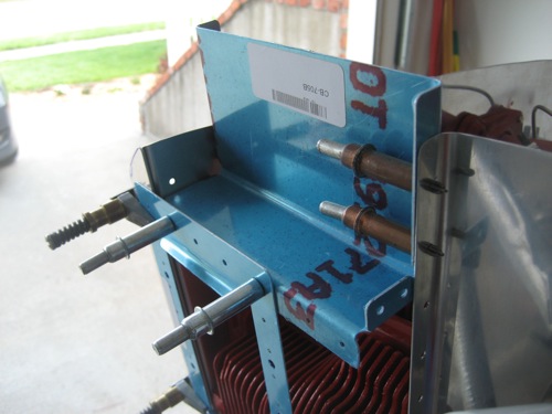
The problem with this is that positions the oil cooler so low that almost half of it is blocked by the cylinder fins. For an RV-8 with its narrow cowl this is your only option, but in a side-by-side RV there is room to mount it higher for better cooling airflow.

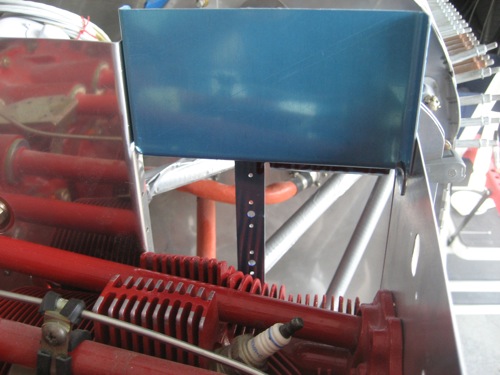
My solution was to cleco the aft flange on CB-705B to the next row of prepunched holes on the oil cooler doubler. This allows the doubler, and thus the oil cooler opening in the baffle, to move upwards a substantial amount.

Obviously the aft flange on CB-705B now blocks an equivalent amount of the oil cooler opening, but there's a solution for that.

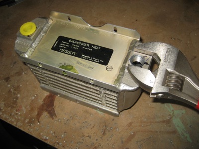
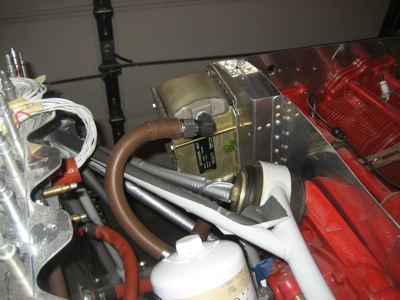
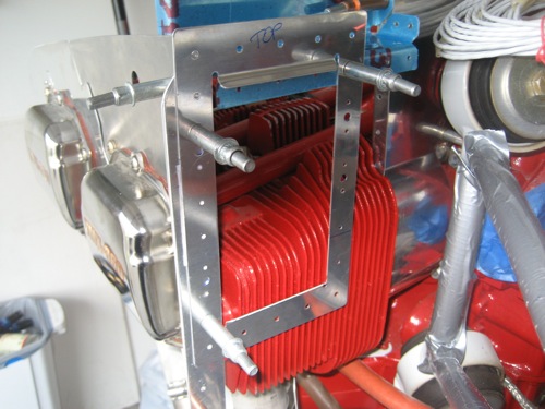
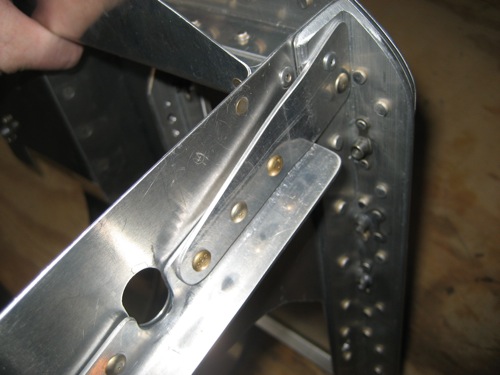
Test-fitting the oil cooler to make sure everything is going to fit. You want to mount it as high as you can to get the most airflow through it, but you don't want it to get so high that it hits the inside of the cowl. There is also a constraint related to the clearance between one of the mounting bolts and the diagonal engine mount tubes. And, you don't want to put the rectangular opening so close to the edge of the baffle that you run into edge distance problems.

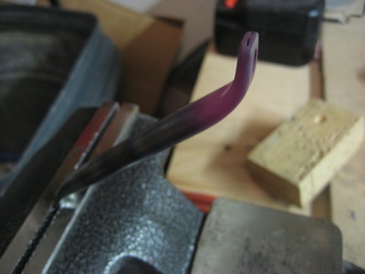
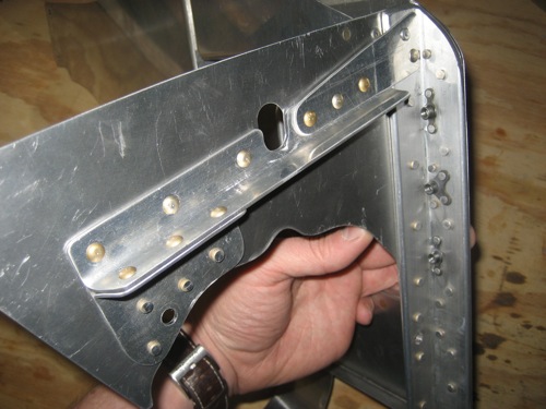
It's typical to have to grind away a portion of the flange where my finger is, to get the proper clearance between the oil cooler and the engine mount.

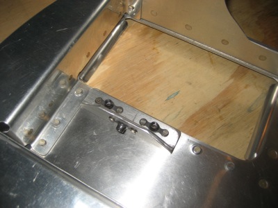
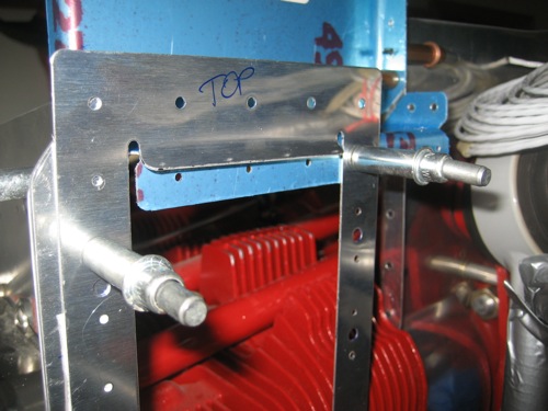
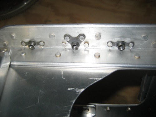
Drilling the doubler to the rear baffle locks in the oil cooler position. The sharp-eyed will noticed that I drilled a hole for a third bolt in the middle of the outboard corner. Since the oil cooler has a hole for a bolt there, I figured why not use it…

The three clecoed holes in the CB-705B flange will be used – the rest of the flange will be cut off.

If you are working on this part of the baffles right now, this photo contains enough information for you to position your CB-705B:

I riveted a piece of 0.040" angle to the top of the horizontal part of CB-705B. It picks up the row of rivet holes along the top of the oil cooler doubler. It's all one big puzzle that you have to figure out how to fit together, while you're also designing the pieces.

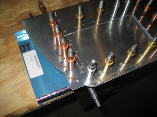
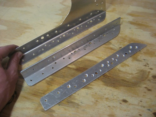
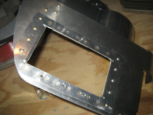
Lots of work between the last photo and this one. I built a number of reinforcement pieces to be attached to the baffles, which I'll detail below. Here's the master shot of all the parts that will be riveted together to form the #4 cylinder baffle and oil cooler mount:

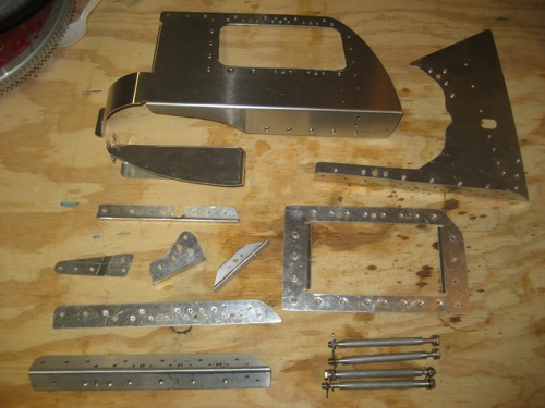
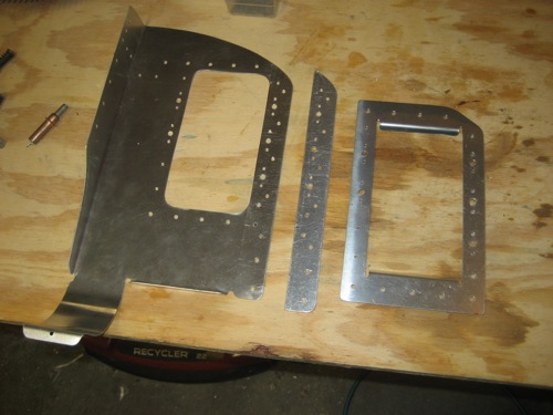
From left to right, this is the aft cylinder baffle, 0.063" spacer, and oil cooler doubler ring. These are all kit parts, no bespoke items yet. Note that the outboard top corner of the doubler ring is substantially ground away to fit the inside of the cowl.

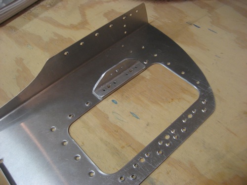
I used a unibit and air nibbler to make the rectangular opening in the aft baffle, using the doubler ring as a template. A complex pattern of dimpling is required to accommodate the different rivets that are flush on one side or the other. The small piece of angle picks up the two inboard bolts on the oil cooler, and will become the attachment point for a diagonal brace later on (a future project).

Another view of the aft baffle and doubler ring. Flush rivet holes everywhere – be careful to pay attention to which way each one faces!

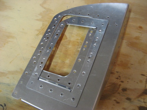
I used a piece of 1/8" angle to stiffen the corner where the aft baffle and outboard side baffles meet. I had to file a radius on the apex of the angle (not visible in this photo) to get it to nest into the bent flange in the corner. The holes where the oil cooler bolts come through are just barely far enough from the angle web to install the nutplates – careful measuring is required here. Note the countersunk holes on the aft side of the 0.063" spacer where it faces the dimpled holes in the aft baffle.

The leftmost and rightmost pieces in this photo are designed to stiffen the side and rear baffles by providing a load path from the oil cooler to the forward mounting screw. This shown more clearly in one of the photos below, keep reading.

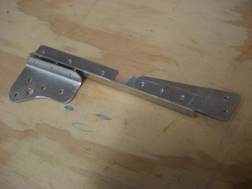
This is what 705B looks like after it's trimmed to fit the cowl, and after the bottom flange has been truncated and a new flange riveted to the top. I also added an extra little tab on the left side to tie it into the cylinder baffle.

Here's a final fit test to make sure everything is going to work. It all seems to line up, thank goodness.

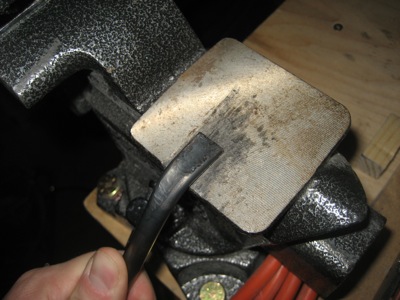
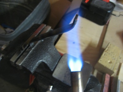
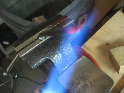
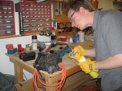
I used a hacksaw, rotary file, and scotchbrite drums to notch the oil cooler flange where it comes close to the engine mount. No clearance problems now, but probably no more warranty either!

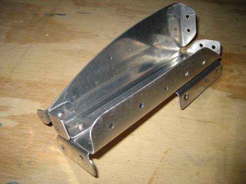
It took hours to rivet the whole thing together. Many of the rivets are hard to get to, and you have to pay careful attention to the order you install things so you don't block access to any of the holes.

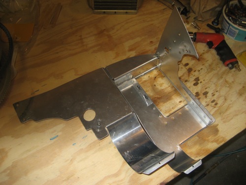
Another view from the side:

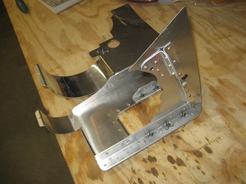
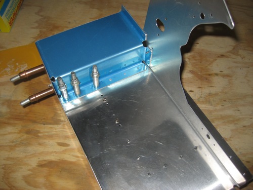
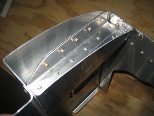
Here's how the stiffener pieces on the outboard side work:

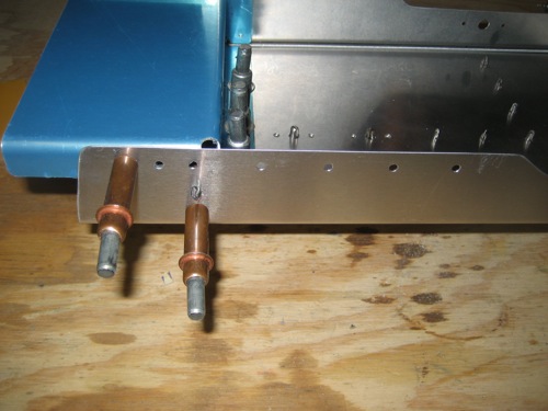
And a closeup of the triangular, joggled attachment at the aft end. The two blind rivets here are the only ones in the entire #4 cylinder baffle, believe it or not – I managed to squeeze or buck all the rest.

Top view:

A view from the inside. Note how the horizontal part of CB-705B is even with the top of the oil cooler opening. That turned out pretty well – not sure why Van's didn't just design the part that way.

Nutplates on the corner stiffener. Some of these rivets were an absolute pain to set properly. It wasn't my best or prettiest riveting work, but it's adequate.

Back side, showing the doubler ring. Rivets are flush where the oil cooler flanges go.

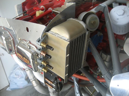
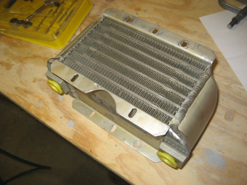
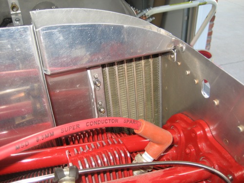
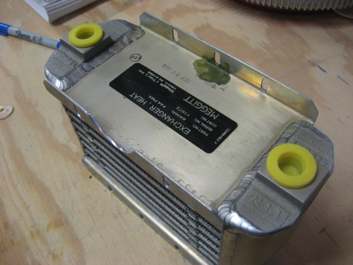
Test-fitting the oil cooler to the completed baffles. I cut and ground a bunch of AN970 large-area washers to spread the load on the cooler flanges, which are made of some very soft type of aluminum and don't seem very strong. Later on I'll prime and paint the steel washers to keep them from rusting where I cut through the cad plating.

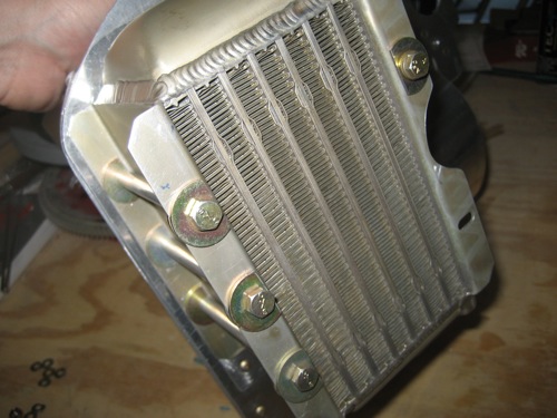
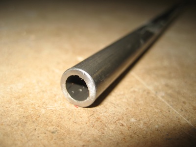
I turned some spacers on my lathe to fit around the bolts and prevent the oil cooler flanges from bending.

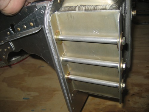
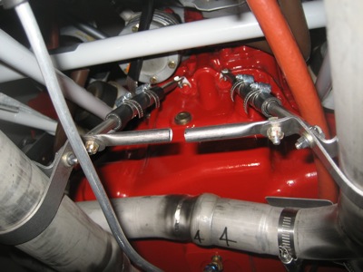
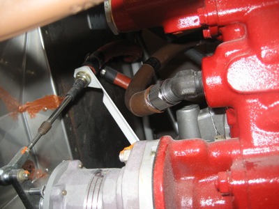
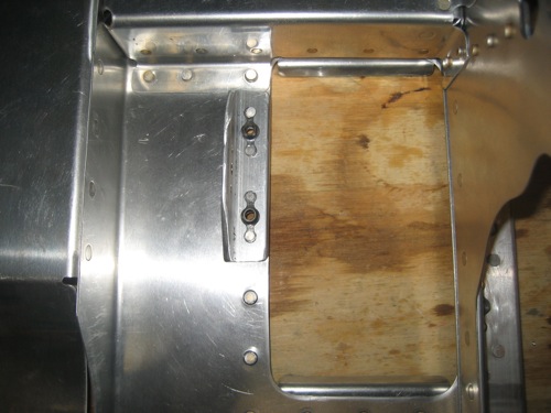
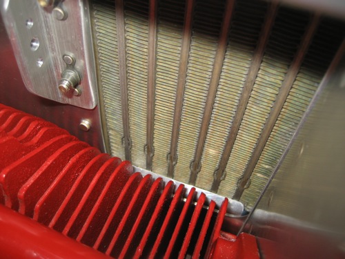
The inboard side has one long bolt (with spacer) and one short bolt where the rear flange was ground away. The lower hole doesn't get a bolt since the cylinder fin would be in the way on the forward side.

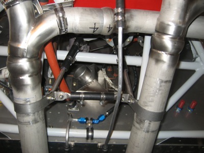
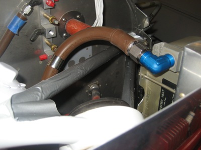
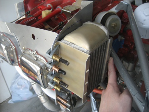
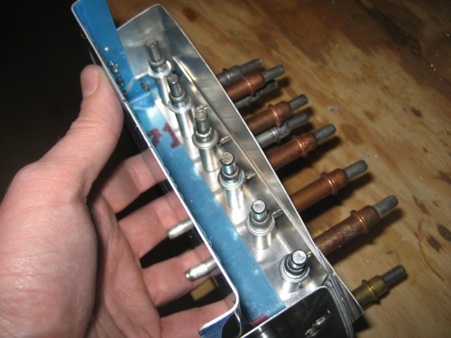
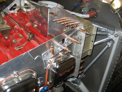
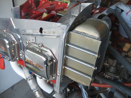
Believe it or not, it's possible to install and remove this whole huge thing with the oil cooler still attached. With the baffle screwed into the cylinder head, the oil cooler mounting is very solid.

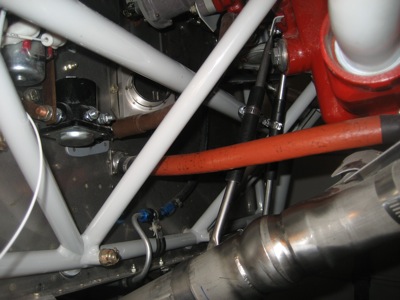
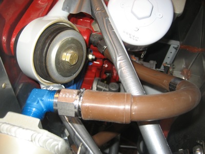
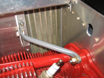
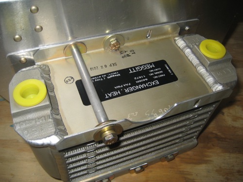
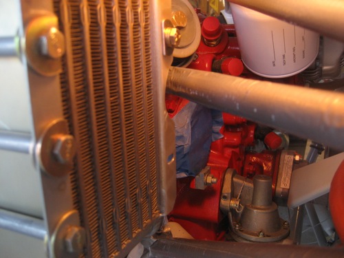
Plenty of clearance between the inboard flange and the engine mount – the plans call for a minimum of 1/2", and I have between 5/8" and 3/4".

Mounting the oil cooler up high allows more of the face to be exposed to the local airflow, which should help with oil temperatures in the summer.

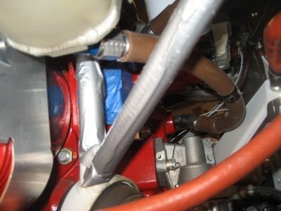
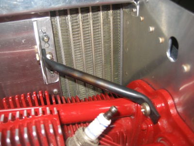
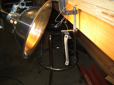
The only part of the oil cooler mounting arrangement that's not as stiff as I'd like is the inboard side, which flops around a bit when shaken. This is only natural, since there's no good way to attach anything to the cylinder between the case and the head. Later on I'll rectify this by running a brace from the flange on the inboard side of the oil cooler to a convenient screw on the cylinder head.

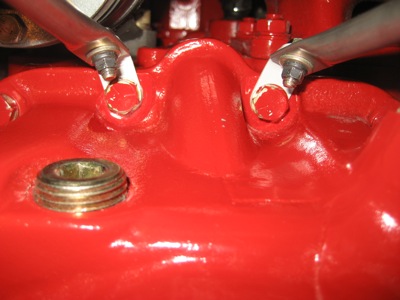
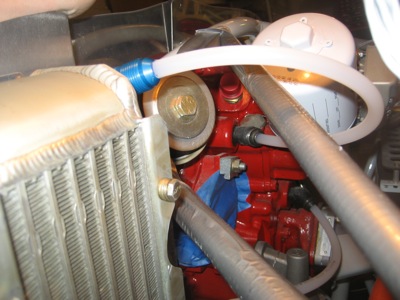
I dabbed a bit of zinc chromate on an area of the oil cooler where I lightly gouged it while trying to fit the short bolt on the inboard side. Got to protect this expensive and vital piece of machinery.

That's it for the oil cooler mounting, for now anyway. A friend once told me, "Keep adding stiffness to the baffles until you can attach a chain and tow the airplane around by the oil cooler." While it may not be quite that strong, it's definitely a lot better than if I'd stuck with the flimsy factory design. Hopefully by putting in the extra effort now, I'll have saved myself some heartburn down the road.