Archive for September, 2006

Subpanel yoga

Sunday, September 10th, 2006

Most of today was spent crawling in and out of the fuselage, laying on my back in weird contortions, trying to get all the holes underneath the panel and subpanel drilled. I have some experience messing around under an RV panel from my previous airplane, so this was just like old times. Still not fun, ugh. For most of these photos, the camera had a better view of what was going on than I did.

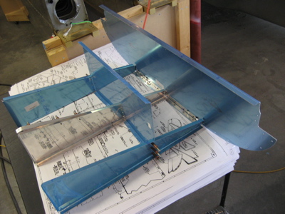
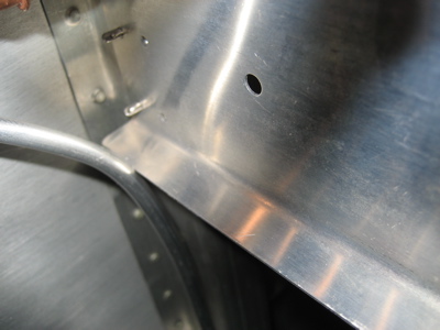
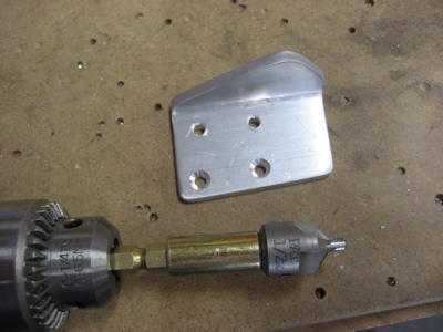
First was match drilling the holes I put in the forward flange of F-7108A to the firewall. After I got the #40 pilot holes drilled, I went back outside the fuselage and drilled them up to #30 from the other side.

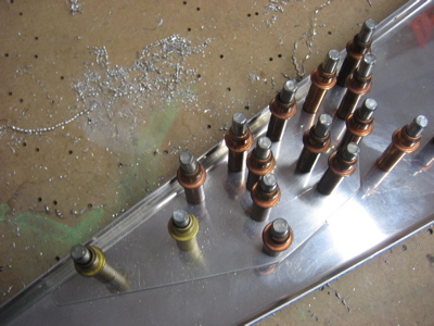
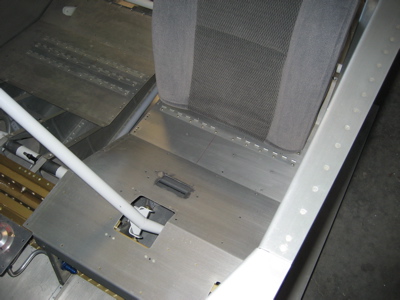
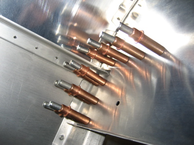
Then came the F-7108C angle that attaches the center rib to the subpanel. No big deal except it was really hard to see what I was doing.

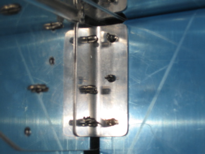
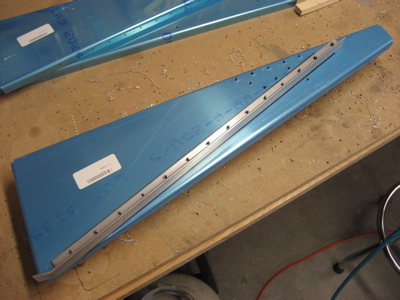
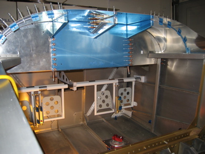
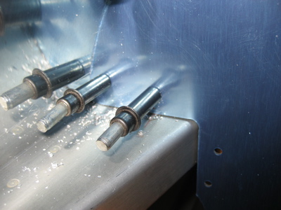
These groups of holes on the outboard subpanel pieces were a pain too.

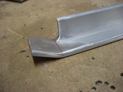
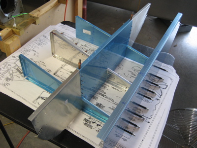
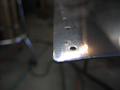
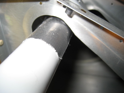
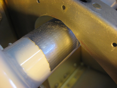
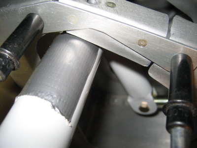
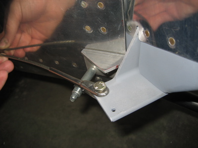
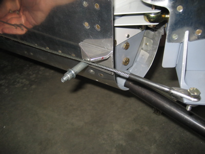
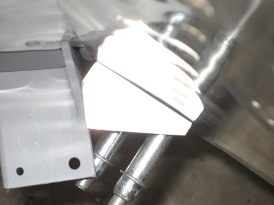
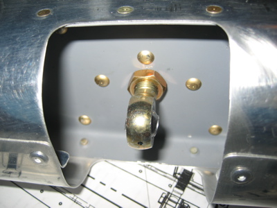
The F-7108C angles were a bit of a poser. These provide the means to attach the panel to the F-721 canopy decks. Pretty simple, except that when you're installing them, you need to have the panel and top skin clecoed in place to position the panel properly, so it's really hard to get in there to drill the holes. I ended up pushing the angles up against the rear of the panel and then using the handyman's secret weapon to stick them in place for drilling.

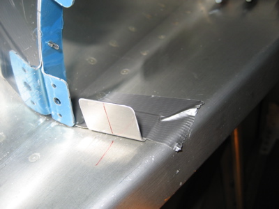
With the angle taped and then drilled and clecoed in place, it was no sweat to drill the #19 hole for the attachment screw. "Remember, if the women don't find you handsome, they should at least find you handy."

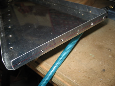
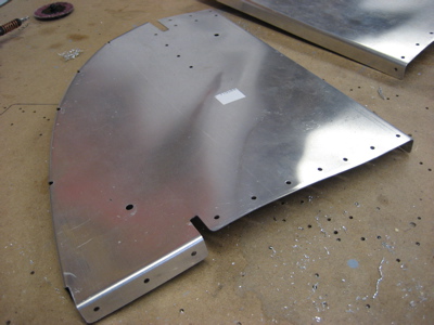
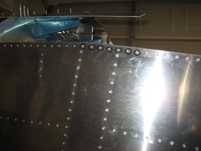
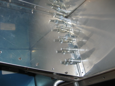
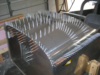
Then I drilled the top skin to the underlying structure. The plans are a little vague on whether or not you should drill the skin holes into the firewall flanges; I chose to do so right now since I couldn't think of a reason not to.

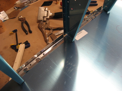
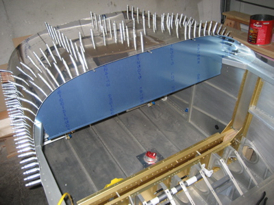
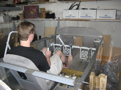
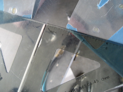
I know all you ladies out there have been writing to ask when I'm going to put up some more pictures of my hairy legs, so I hope today's update does not disappoint. I put the pilot's seat back in and adjusted it to its most comfortable position, in order to measure the clearance between my knees and the bottom edge of the stock instrument panel. It looks like with my feet on the rudder pedals (imaginary, in this photo) I will have somewhere between four and five inches of clearance between my knees and the panel. This is good news, because it means I will probably be able to install a slightly oversized panel such as the Affordable Panels XL panel. That means more room for delicious avionics.

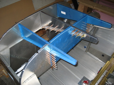
Then it all came apart for deburring. Funny, the photos above don't make it look like I did much today. It took a long time, though, because most of it was really hard to get to. At least I was able to contemplate the meaning of life while performing many airplane-based yoga poses.

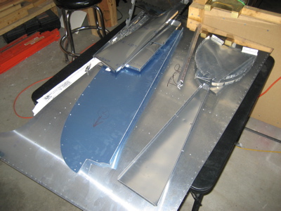
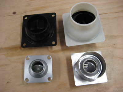
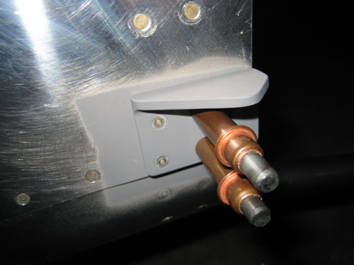
Also, since it's germane to this discussion of the instrument panel – I got my air vents recently. The factory-supplied plastic vents are in back, the new (expensive, ugh) aluminum vents are in front. They seem well-made. I think I'll end up needing to make special mounting plates for them, though.

Working on upper forward fuselage

Saturday, September 9th, 2006

Lots of work on the upper forward fuselage this time around. This area includes the forward top skin, the instrument panel, and all the hidden structure underneath that supports the panel and gives stiffness to the forward fuselage area.

First I cut and fluted the F-7103C angles that attach the middle of the top edge of the panel to the skin. (You have to flute 'em to make them match the contour of the curved panel) Then I drilled the three holes per side that will eventually take a screw and nutplate to hold the panel on. The blue things in this photo that are perpindicular to the panel are the subpanel ribs, which I clecoed in place to get the F-7103C fit right.

Next up is the F-7109 doubler plate. This was the only piece of 0.063" I could find in my stash that was big enough to make this guy out of, which seems like kind of a waste, but oh well. If I need another piece of comparable size I can always go up to Airparts.

Here it is after being cut out and deburred.

The F-7108B angle is next. I actually did have to go up to Airparts for this one, since I couldn't find any 3/4"x3/4"x1/8" 6061 angle in my stash anywhere. Perhaps I used it for something else. Anyway, you have to cut off part of one of the flanges (remembering to use a nice radius instead of a right angle) and then bend the remaining tab to match the angle in the plans.

Here is is being match drilled to the F-7108A center subpanel rib. This was a bit fiddly to do, since you have to get everything clamped down so that a centerline drawn on the angle is lined up with the prepunched holes in the rib. It took a few iterations of clamping before I was happy with the alignment.

Then the F-7109 plate goes on the other side of the subpanel rib and is match drilled into the rib and angle. The purpose of all this extra material is to provide a nice beefy area for the roll bar brace to attach. The angle ties the roll bar into the firewall and the plate reinforces the rib where the bolt holes (gold clecoes here) go through. I drilled the bolt holes undersized to #14 right now, on the assumption that once the roll bar weldment is in place I'll be coming back through with a reamer to make them perfect.

The forward flanges on the F-7107 L/R subpanel ribs are prepunched, but the flange on F-7108A is not – nor is the firewall prepunched where the center rib attaches. The plans don't specifically say how or when to put holes here, but I figured I'll have to have some eventually, so I put some #40 holes here for now. I'll match drill to the firewall and size them up to #30 later on.

Here's the panel, center subpanel, and subpanel ribs clecoed together to check the fit. Not bad.

The F-7105B outboard subpanels, however, are a joke. The forming process leaves them more warped than the first track on One Hot Minute.

I attacked the offending pieces with hand seamer and fluting pliers, and was able to get them to be somewhat more planar. They still have some waviness, but it seems to mostly disappear when I cleco them to the rest of the structure. I'm hoping that when I rivet the whole thing together it will all be pulled into line.

Here I've clecoed the upper forward structure (sans panel) into the fuselage. The outboard subpanel ribs are clecoed to the prepunched holes in the firewall, but the center rib is just floating free.

Got a little bit of interference between the starboard fuel vent line and the subpanel. No big deal, I can tweak the bend on that line when I install it for good.

I had to drill out the circled rivets, since the upper forward skin for the slider has to attach there too. I think the quickbuilders got a little carried away, or else maybe they just automatically build the fuselage like you're going to build a tip-up canopy. (that would explain the presence of F-705G when it comes off the boat)

In this photo you can sort of see where I used the edge roller to put a downward (inward) bend in the left and right edges of the top skin. I've seen some RVs where the tension in the top skin tends to lift it up at the longitudinal rivet line, so I figured I'd head it off at the pass, so to speak.

I clecoed on the top skin to check the fit. You really have to grunt to get it to go around the curve, but everything seems to line up. I also clecoed in the F-7103B attach angles.

The panel also seems to fit okay.

I still have to get under there and drill a bunch of miscellaneous brackets and so forth, which will be a painful yoga exercise.

Worked on pitch controls

Monday, September 4th, 2006

Not much got done on the airplane today because I was tired. However, I did figure out what was wrong with the F-789 forward elevator pushrod… it's not that it was too short to allow sufficient down elevator travel, it's that the control column was hitting on the seat ribs. I dremeled out some small bites from the F-716 seat ribs, just enough to allow full forward stick plus about 1/16" extra for clearance.

Another photo of the other side. The duct tape is to protect the finish on the control column.

I likewise had to trim the removable parts of the two center seat ribs:

Once I had full stick travel, I put in the pilot's stick and seat in order to adjust the neutral stick position. Man, these seats are comfortable as heck.

Here's me doing ergonomics testing. I was in and out of the fuselage a half dozen times before I got it the neutral point adjusted where it fell easily to hand. The pushrod has a little more than the minimum required thread engagement, which is good. If you're reading this and you haven't fabricated your F-789 yet, do yourself a favor and make it about 1/4" longer than what the plans call for.

Yes, I made airplane noises:

Made rudder stops

Sunday, September 3rd, 2006

If I worked at a real airplane factory, I'd get fired for taking like eight hours of work over two days to make these stupid little rudder stops. Of course it doesn't help that the design requires each set of stops to be tailor-made to the individual aircraft. I spent a huge amount of time measuring, making and discarding test pieces, and fiddling around with templates. Out of absentmindedness or frustration I forgot to take any photos of this process, so here's a shot of the first rudder stop I was able to produce that actually fit:

You can see that I've temporarily installed the rudder cables to make sure that the rudder stops and cables don't get tangled up at any point along the full swing of the rudder.

Here's an overexposed overhead view showing the angle the rudder horn is at when it hits the stop. Lots of cutting and filing to get to this point.

It means nothing unless it has that swing – when the rudder hits the stop and the elevators are neutral, it's just a shade over an inch from the rudder to the inboard corner of the elevator trailing edge. Plenty of clearance to keep the tail surfaces from banging together, and slightly more travel than is called for in the plans. Extra rudder travel is good, it means extra rudder authority. I've heard of some people making this dimension more like 1/2", but that seems like cutting it bit fine to me.

After I was finally satisfied with the fit, I rounded off all the corners and made the stops look pretty, and countersunk the rivet holes. These two I was able to do with the countersink cage; for the two that are closer to the flange, I used this setup to make the countersinks freehand.

I primed the stops and the skin underneath, then riveted them halfway on. The plans call for CS4-4 blind rivets in the front two holes. I used CherryMax CR3212-4-4's instead since I have a whole drawerful; the literature says they are something like 3x stronger in shear. The aft two holes will have to wait for now, since I can't squeeze those rivets until I remove the vertical stabilizer.

This photo is to remind me that I haven't torqued any of the control surface jam nuts yet – my torque wrench has a 1/4" drive and my crow's foot wrenches take a 3/8". Time to go to Sears!