Archive for February, 2007

More empennage fairings

Sunday, February 18th, 2007

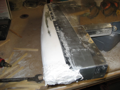
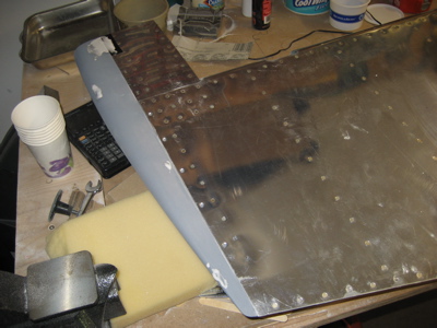
Today was an all-fiberglass day. Sorry, no action shots – hard to hold a camera with sticky fingers.

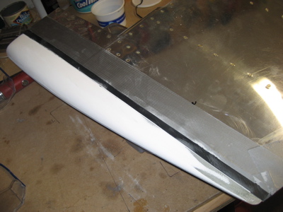
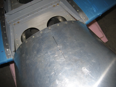
I sanded most of last night's primer off of the top rudder fairing, then put another glob of filler on the front where it still needs to be built up. My favorite tool for this kind of sanding is a 3" red scotchbrite disc in a die grinder turned down to low pressure. I also use a 60 grit sanding block where necessary, but power tools make the job go faster.

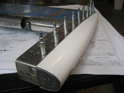
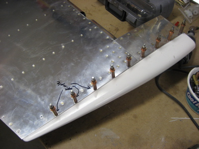
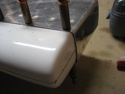
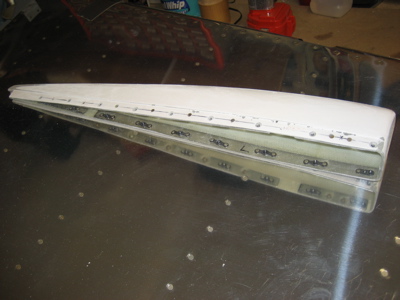
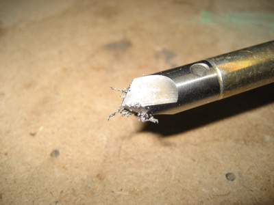
While the rudder fairing was curing, I got out one of the elevator tip fairings and started playing with it. The lead counterweight at the front is going to throw some sand in the gears of my plan to make removable empennage tips. It is tempting to permanently attach the elevator tips and just glass over the counterweights, but I'm still going to try to make them removable because I love a challenge. (Mary would probably say that I'm just plain stubborn)

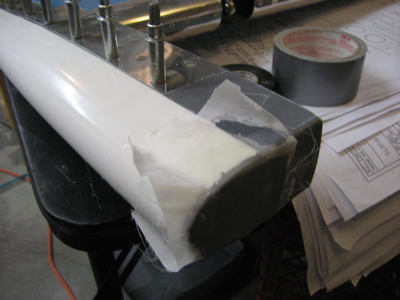
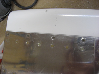
I laid up three layers of lightweight cloth, sufficient to cover over the open end of the fairing where the counterweight lives. It's not much to look at right now because the peel ply is blocking the view. Underneath is a layer of electrical tape to prevent the fiberglass from sticking to the lead. With any luck this will form the starting point for a closed-end fairing that will cover the counterweight but will still be removable – we'll see tomorrow.

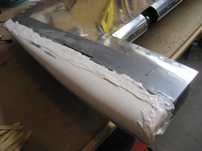
Hours later, the second coat of filler on the rudder was dry, so I proceeded to sand away at it. The shape is almost there now – just needs one or two more layers.

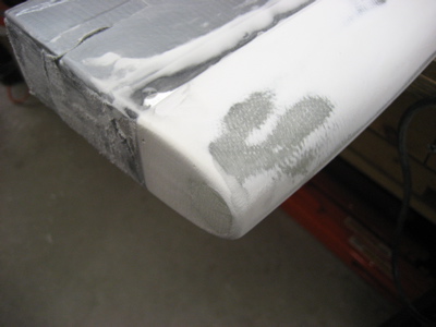
After shooting a coat of primer to help me check the finish, I put more filler on a few spots to fix some of the more egregious pinholes. My goal is just to get the basic contour correct – I'll leave the detailed surface finish work to the painter.

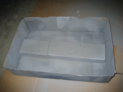
In the middle of all this, I bought and put together this particle board file cabinet for Mary. I found myself thinking how awesome it would be if airplanes were put together with quarter-turn fasteners. I'd already be flying!

Working on top rudder fairing

Saturday, February 17th, 2007

I decided that I should work on the empennage tips next, because it will be a lot easier to mess with them while I have the tail removed from the fuselage. Once the engine goes on I'll have to keep the tail attached to prevent the fuselage from tipping over on its face, so I'm trying to get as much done on the empennage while I have the opportunity.

For no particular reason I decided to start with the top rudder fairing. I trimmed the flanges enough to get the part to fit onto the rudder, and match drilled #30 holes through the skin into the fiberglass.

It isn't a terrible fit, although it is quite a bit shorter than it needs to be. I'll have to build up the forward face with filler.

The plans have you attach the fairing to the rudder skin with flush pop rivets. A lot of people use filler to make their fairings match the contour of the empennage surface, then use a layer of fiberglass to hide the joint between the aluminum skin and the composite fairing. Me, I really like the look of a well-fitted fairing with a perfect, visible seam between the two parts, so I decided to steal Randy Pflanzer's method. He made his fairings removable by using 4-40 screws and nutplates instead of blind rivets, which lets you take the fairing off to clean up the join line.

I riveted nutplates to the fairing, using a thin strip of alclad as a backing strip to keep the rivets from pulling through the fiberglass. On the first side I did (facing down in this photo) I used the same rivets to attach the nutplates to both the aluminum and the fiberglass. That turned out to be a pain to do properly, so on the other side I first riveted the nutplates to the aluminum strip, then riveted the strip to the fairing with one rivet between each pair of screw holes. That way turned out a lot better, since I could do the tricky riveting of those tiny little nutplates out in the open where I had better access.

By the way, the gaps in the alclad strips in the photo above are there because I made the them out of scrap and I didn't have anything long enough to span the full length of the fairing.

Here's an initial view of how the fairing looks when screwed in place. A #4 flush screw fits in the same dimple as a 1/8" rivet, and I really like the look of the visible fasteners. There is about a 1/16" gap along the join line, which will need filling.

I protected the rudder skin with a layer of electrical tape (very thin but rugged enough to resist sanding) and some duct tape too for good measure. Then I used some 60 grit to knock down the high spots in the fairing. The very tail end was the worst spot, as the fairing was quite a bit thicker than the rest of the rudder back there.

Then I mixed up a batch of epoxy and microballoons that was about the consistency of peanut butter, and slathered it all along the join line, making a special effort to try and force it down into the gap. I also tried to build up a big glob of filler on the forward face where the fairing is too short, but I expect I'll have to revisit it a couple more times in order to get enough material where it needs to be.

I'll let the whole mess dry overnight, then sand off all the excess and see where it leaves me.

Oh yeah, while I was doing stuff in the airplane workshop I installed the eye bolts through the firewall, to which the rudder pedal return springs will attach.

Started removing the tail

Sunday, February 11th, 2007

I decided that I'd better get the tail permanently mounted before the engine arrives, since without the weight of tail back there the engine will tip the airplane over. But before I can put it on for good, I need to take it off once more in order to finish up a few chores. Tonight I got as far as removing the vertical stabilizer.

I squeezed the remaining rivets on the rudder stops that were previously blocked by the VS spar. I also smoothed out a few scratches in the aft bulkhead that were a result of the initial stabilizer fitting. Looks like the primer dripped – doh.

I attached the nutplates for the fairing to the vertical stabilizer:

…and one to the fuselage just in front of the tail:

Working on rudder cables

Sunday, February 11th, 2007

I had previously put the rudder back on the airplane to demonstrate something to another builder, so while I had it on I decided to work on the forward ends of the rudder cables. They're connected to the pedals via small 4130 steel links that you make from raw stock, and since I'm the one building this contraption I get to size them in such a way that the pedals' neutral position is set up just for me. I put the seat cushions in and spent a fair amount of time playing with pedal positions and angles until I was happy. Using tie wraps as temporary stand-ins for the F-6119 links was a good way to quickly experiment with different link sizes.

In a rare example of intelligence and foresight on my part, I drilled out this rivet on both sides of the firewall. I'll put an eye bolt in each hole to provide a place to anchor some pedal return springs, should I need them. It's much easier to plan for this now while I still have decent access to the back side of the firewall. The springs will go between the eye bolts and the pivot bolts on the two innermost pedals, to keep the rudder from flopping around on a windy ramp. I should also be able to size them appropriately to dial in a bit of rudder trim if I need it.

Because they're installed in pairs, I wanted to ensure that the hole-to-hole spacing was the same for all four links. I drilled them together so they're all identically sized.

Deburring ferrous material makes little magnetic whiskers. Science is fun!

One more test to make sure these are the right length. The pedal angle is good and I have to point my toes slightly to get up on the brakes, which should help prevent inadvertent braking (especially unwelcome in a taildragger!).

I rounded off the corners all nice-like, and then because these are steel pieces I primed them and gave them a coat of enamel to protect against rust.

Here's the finished product, with cotter pins installed. Note that they have you use AN23 clevis bolts here, presumably because the low profile head has less of a chance of catching on your shoe.

It took a surprisingly long time to make these four little pieces. I spent a lot of time fooling around with different rudder pedal positions, which involved repeatedly unbolting, repositioning, and re-fastening the pedal mounting blocks. In the end I wound up using the middle of the three available positions, which was where the pedals were mounted before I began this exercise. Oh well.

For reference, I'm about 6'1" and I made the pedal angle fit me well by using the middle pedal attach position and using a hole-to-hole distance on F-6119 of 1.5 inches.

The last thing I did on the rudder cables today was to pay some attention to the bushings through which they pass as they head from the pedals to the tail. All RV's make a kind of sawing noise as you work the rudder pedals – that's the sound of the cables sliding through the plastic bushings. Other aircraft use pulleys for this, and the bushings Van's uses are a little cheesy but they work. A recent issue of the RVator suggested cutting a slot in a smaller bushing, slipping it over the cable, and inserting it into the bigger bushing – the idea being to provide more material for the cable to saw through before it starts eating into the bulkheads. Of course, you inspect these every year during the annual condition inspection, and they last for years, but I thought it seemed like a good idea anyway. I used an Xacto razor saw to slit a dozen or so bushings and popped one into every bushing from the pedals to the tail.

Mounted secondary strobe power supply

Saturday, February 10th, 2007

I mounted the power supply for the red belly strobe next to the main one, using basically the same type of bracketry as I used to mount the ELT:

Astute readers will recall that this box is designed for ultralights, so as such it has less power output than a real-airplane strobe power supply. In this case that's exactly what I want, since I don't want my belly strobe to be quite as blinding as the real three-point anticollision strobe lights. I actually hooked up the 70821 strobe head and gave it a try before I installed this thing permanently. The flash rate is lower than the main strobe power supply, and the pulses seem less intense. Excellent.