Archive for the ‘Baffles’ Category

Left crankcase baffle

Sunday, February 27th, 2011

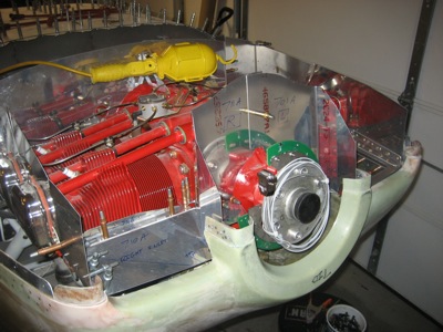
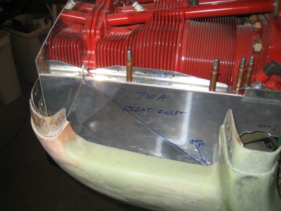
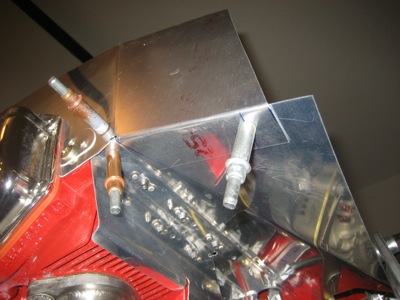
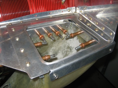
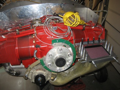
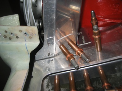
Well, this is a fine mess… there's no room on the left inlet ramp for the brackets that are supposed to attach to the left crankcase baffle:

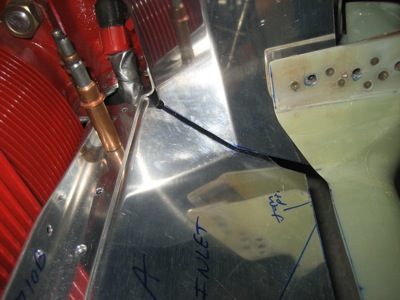
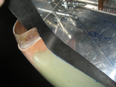
Adding insult to injury, I accidentally trimmed off too much of the crankcase baffle while I was trying to get it to fit, resulting in a too-large gap behind the cowl inlet:

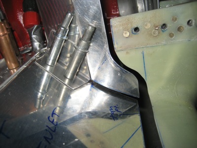
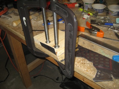
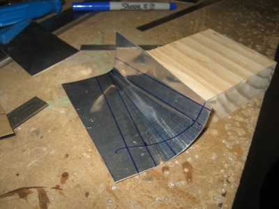
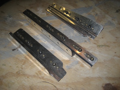
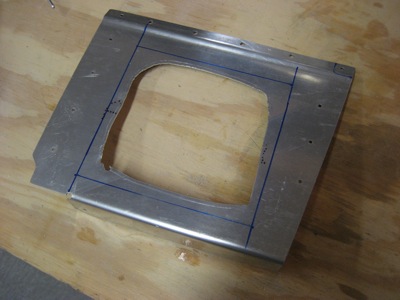
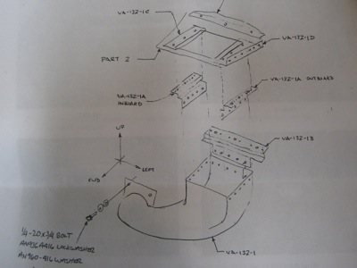
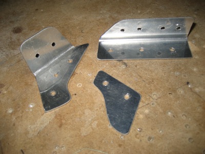
I spent a day scratching my head and testing various ideas to make this all work, before I finally came up with something that I was happy with. I started by making two brackets and a filler piece:

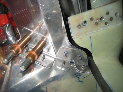
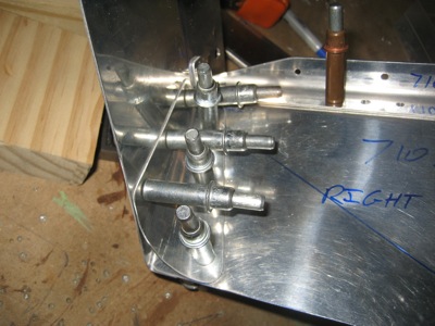
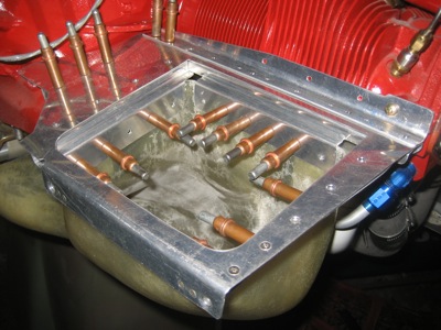
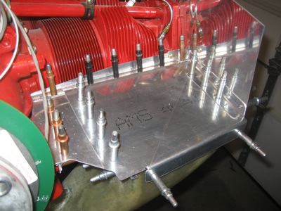
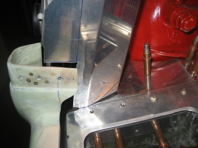
Here's how the two brackets are attached to the inlet ramp. Each one picks up one of the rivets in the other bracket that runs longitudinally on the bottom side. You can also kind of see how I ground away the edge of the air filter retaining ring to make it clear the crankcase baffle.

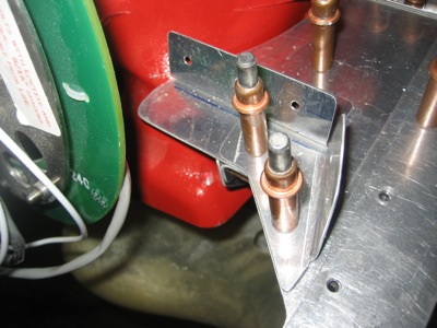
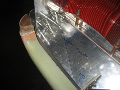
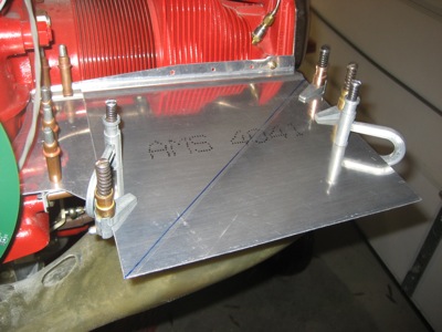
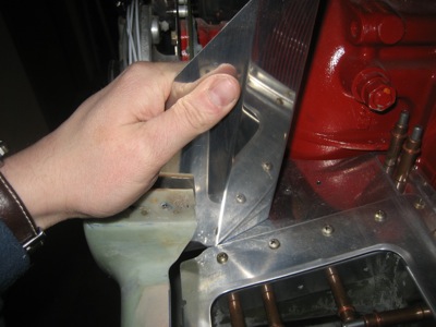
The funny-shaped bracket tucks under the baffle and attaches on the back side:

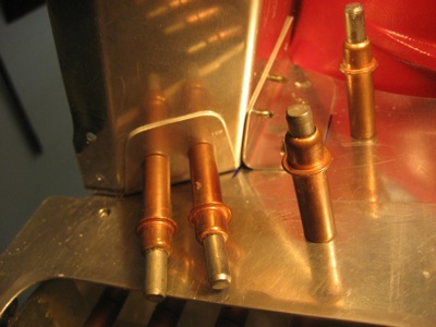
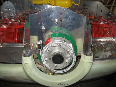
Another view of the same area:

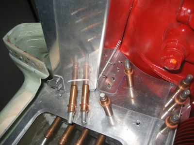
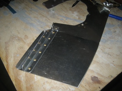
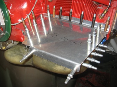
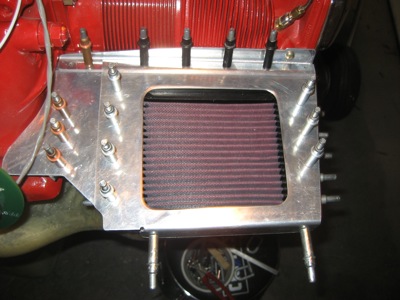
The filler piece rivets to the baffle and erases my trimming mistake:

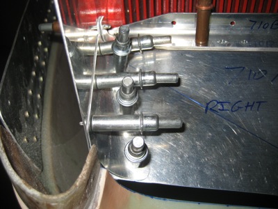
It all basically works together, and I verified that there is still just enough room to remove and reinstall the air filter and bracket. Stupid air filter, making things entirely more complicated than necessary, again.

Right crankcase baffle

Saturday, February 26th, 2011

Next in the ongoing baffle saga are the crankcase baffles. These stick up behind the flywheel and stop cooling air from leaking around the spinner. In this photo I've already spent an hour of iterative trimming just to get them to fit on the engine.

These are obviously way too tall right now – they'll get trimmed substantially later on. The wire wrapped around the crankshaft goes to the tach pickup for the Lightspeed ignition. I tie-wrapped it out of the way so I wouldn't accidentally cut it while working on the baffles.

I ended up with more of a gap than I wanted between the inlet ramp and crankcase baffle on the right side:

Per the plans, I made a little bracket to attach the two baffle parts together. I also rounded the back of the cowl inlet a bit, and trimmed the crankcase baffle to match.

I didn't like that gap being there, nor how flimsy the front part of the baffle was, so I made another little odd-shaped bracket for that location:

Right baffles

Sunday, February 20th, 2011

Working on the right side inlet ramp is much easier than the left, since there's no air filter to deal with. I roughly trimmed the inlet ramp and #1 cylinder baffle until they were short enough to put the cowl on, then bent the inlet ramp to match the contour of the cowl inlet.

To bend the flange on the cylinder baffle, I had to use a hammer and a wood block since the geometry wouldn't work with my little bending brake. Yes my C-clamps are big enough, why do you ask?

To provide a smooth surface for the rubber material to seal against, you have to make this conical gusset out of sheet aluminum. That was kind of a fun little task… surprisingly, bending it by hand over a wood block really does work.

Most of rivets connecting the two baffles are common with the gusset, but I went ahead and put in one extra rivet hole so I could hold things in alignment. That made it a lot easier to get it all fitted properly without requiring three hands.

Here's the gusset after being fitted and trimmed:

I cut the baffles back to create a 3/8" wide gap between the baffles and the cowl. Amazingly, this dimension appears nowhere in the plans, but the consensus is that 1/4" is the minimum and 3/8" is about right. I could only get 1/4" on the left side due to the air filter being in the way, but on this side I decided to go to 3/8".

You have to trim the outboard edge of the inlet ramp so the cylinder baffle ends up just outside the edge of the cowl inlet:

Here I'm using a scrap piece of rubber airseal material to demonstrate the desired effect. This stuff will be attached to the cowl inlet lip, and will seal against the baffles to keep air from escaping. Note how the conical gusset allows the rubber material to transition smoothly from horizontal to vertical without disturbing the seal.

Left baffles

Sunday, January 30th, 2011

Cold in the garage and I didn't feel great, so I didn't get as much done this weekend as I wanted. I did drill all the holes in the left inlet ramp, side baffle, and air filter parts up to final size. Then I deburred all the parts, and installed nutplates on the brackets that attach the inlet duct to the baffle:

Another trial fitting. Note the two countersunk 4-40 screws at the outboard forward corner – I found that these are necessary to keep everything together.

I bent a flange on the bottom of the left baffle piece, to add a bit of extra stiffness, then riveted the various angle brackets to it.

Here's what it all looks like when it's screwed together, minus the air filter of course. This is way overbuilt (you could probably use it as a tow hitch!) but at least everything fits and it's not going to come apart. When it warms up a bit, I'll glue and then rivet the bracket thingies to the air duct, and patch the holes I had to grind in it to make it fit.

Next chore: The right inlet ramp and baffle! Luckily there's no air filter on that side, so hopefully it will be easier.

Air filter retaining ring

Sunday, January 23rd, 2011

When last we saw the air filter, its brackets were fitted but there wasn't anything to hold it in yet. So earlier this week, after doodling various methods for securing the filter, I drove up to Airparts on my lunch break to buy a sheet of 0.040" aluminum. Then I cut out a nine-inch square and bent a lip and a joggle into it. Since I only have a small hand brake and not a real joggling tool or any kind of press, this was harder than I thought.

I put a diagonal bend into the new piece to match the inlet ramp:

Then I bent the excess material at the front end into a 90-degree flange. This was kind of a chore, as I wanted the two flanges at the front to match up exactly, as well as for the joggled lip at the back to fit over the transverse stiffener angle. It took some doing to get it all fitting properly. Once I was finally satisfied with the fit, I match drilled the holes through the filter brackets and inlet ramp, plus two more holes at the front to tie the front flanges together.

To attach the side baffle to the inlet ramp and filter retainer, I used some 0.040" angle. This will be riveted to the side baffle, and then the whole stack of angle / retainer / inlet ramp / filter bracket will be held together with screws and nutplates.

I marked the outlines of the cutout, and rough cut it with the air nibbler:

To cut the hole to the final size, I used the drill press like a mill again, followed by files and various deburring tools.

Still a lot of details to finish up, but now at least I have the air filter mounted in its brackets, and the retaining ring that will hold it in place is mostly built.

By the way, this is what the plans for the inlet air duct and filter look like… xeroxed pencil drawings! The best thing to do is to use them to understand what the end goal is, then put them aside and figure out on your own how to build the parts you need to make things work.