Archive for November, 2007

Radio Tray Fitting

Sunday, November 18th, 2007

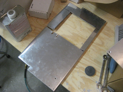
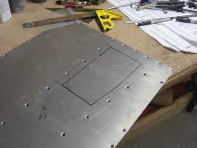
After much examining and head-scratching, I decided to lower the entire radio stack by 3/4" – you'll see why in a minute. This in turn necessitated removing another chunk from the subpanel, cutting it almost in two. Ouch.

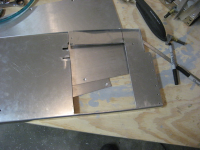
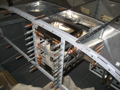
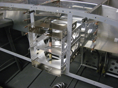
Here are the trays in the new position. I'm planning to fill the extra 3/4" of space above the audio panel with annunciator lights.

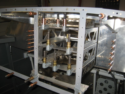
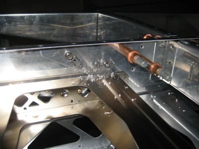
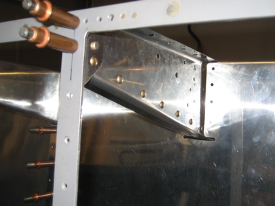
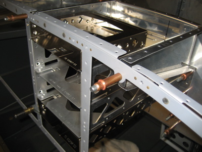
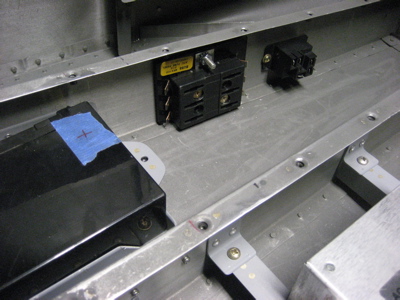
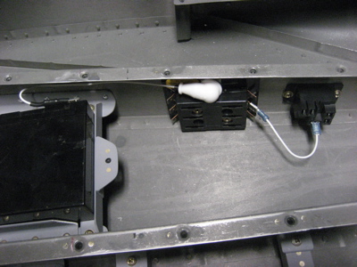
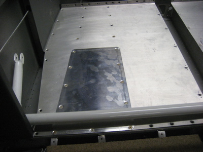
And here's why I decided to lower the radio stack… notice the two big holes in the center subpanel rib, roughly in the center of this photo? Those are where the bolts go to attach the roll bar brace to the subpanel structure. With the radio stack all the way at the top of the panel, the tray for the audio panel would have interfered with these bolts in a big way. Dropping the radios creates a clear area for the bolts, although with the top skin riveted on and the radio trays installed, I'm still not going to be able to get a wrench on this side of the bolt holes.

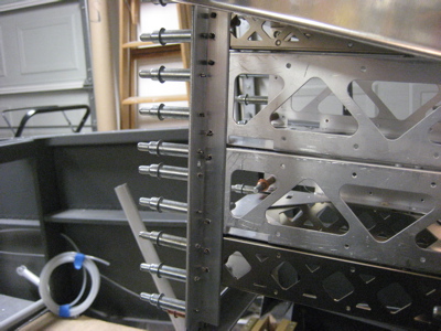
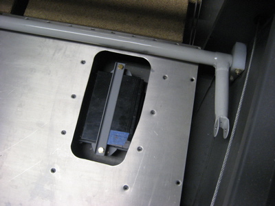
After a lot of measuring, clamping, and adjusting, I started fitting the radio tray attach angles. There's a piece of 0.063" angle running vertically at each of the four corners of the radio stack, through which the trays will attach to the panel frame and subpanel.

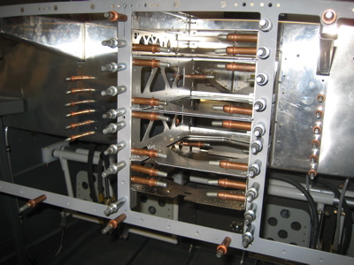
Here's a view of the back side of one of the aftmost (cabin-side) angles. The angles will be riveted to the panel frame, and the trays will attach to the angles with countersunk screws inserted from inside.

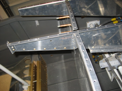
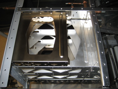
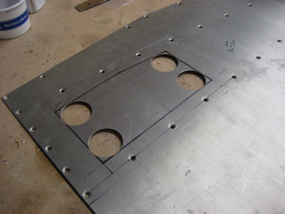
Happily, the nav/com and transponder trays have pre-drilled mounting holes located at exactly the right place to attach to the subpanel in an RV-7, if you orient the attach angle this way (flange on the forward side of the subpanel). With the trays attached to the subpanel in this way, they effectively become part of the structure, making up for some of the stiffness lost by cutting big chunks out of the subpanel.

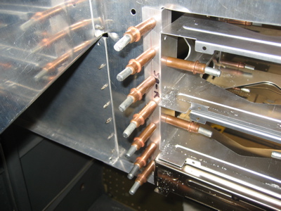
I may yet decide to rivet another piece of angle to the bottom of the subpanel to stiffen it up, but it seems pretty strong already. You can actually grab a radio tray and use it to move the whole fuselage around the garage floor.

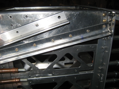
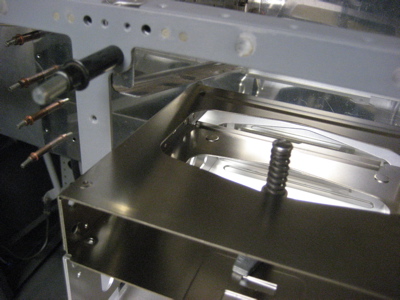
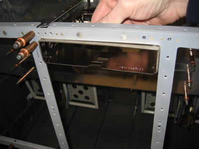
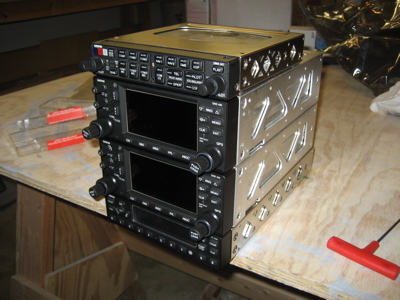
The exterior surfaces of the radio trays are lined up flush with the cabin side of the panel frame. The faces of the radios will stick out about a tenth of an inch further, and with the panel itself being made of 0.080" material I should end up with very little gap between the radios and the panel. A little too much clearance is better than not enough, since that would prevent the radios from being inserted all the way into their trays.

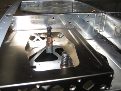
In this photo you can just barely see a hole near the lower flange of the (modified) subpanel rib. A screw will go through there and provide another attach point for the audio panel tray – the audio panel is shorter than the other radios, and doesn't extend far forward enough to be attached to the subpanel. I made a little spacer out of 1/8" aluminum to go between the right side of the rib and the left side of the audio panel tray.

I fitted nutplates to the two aforementioned bolt holes, so that I'll be able to insert the bolts from the relatively unobstructed left side of the center subpanel rib:

I didn't get as much done this weekend, as I'd planned, but I'm still glad I got the radio trays fitted. The next step is to rivet the subpanel structure into the fuselage for good, but there's a short list of related minor chores that have to be taken care of first.

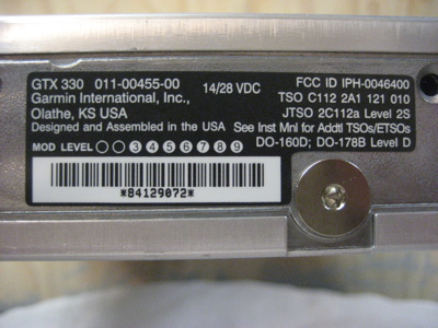
Also: I think I will enjoy having the traffic features of the GTX 330 transponder, but if I knew then what I know now, I would probably have chosen the much smaller GTX 327 instead. Then I wouldn't have had to do nearly as much chopping up of the subpanel, even with the two 430s in the radio stack. Or, I could have kept the 330 and gotten rid of one of the 430's, making the radio stack much shorter. But anyway, I'll make it work and it will be pretty nifty when it's done.

Radio trays

Sunday, November 11th, 2007

My avionics arrived – lots of big heavy boxes:

I extracted the radio trays and tried test fitting them to the panel. Immediately it was apparent that things were not going to be easy… the flange on the center subpanel rib (F-7108A) was totally in the way of the radio trays.

Here's a closeup of the problem, in which you can also see that the little ear by which the panel frame attaches the aft end of the rib is also in the way of mounting the avionics up high. I wish I'd had the Affordable Panels guy move my radio stack a half-inch to the right instead of lining up the left edge with the subpanel rib, because then I wouldn't have any fit problems. Anyway, I'll work with what I've got.

I thought about simply putting the avionics at the bottom of the radio stack cutout and filling the top few inches with switches or annunciators or something, but one look at the subpanel killed that idea. Since the subpanel is shorter than the panel itself, moving the radios down too far would mean that the entire bottom of the subpanel would be cut in two. That seems like it would weaken the structure unnecessarily, so I resolved to find a way to make the avionics fit at the top of the stack.

Here is the result… I cut off the aft flange and about a foot of the bottom flange, then riveted replacements made of 0.032" angle to the opposite side of the rib, out of the way of the radios. I also ground the little mounting ear off of the panel, and moved the screw hole to a new nutplate that's a half-inch to the left of the previous location.

Another view of the modification. You can see that the new bottom flange shares one rivet apiece with both the new aft flange and the remaining part of the old bottom flange, which makes it all pretty stiff. The whole thing is right next to a big piece of 1/8" angle (F-7108B) anyway, so I doubt it really matters whether or not this flange is even here, but it makes me feel better to have it. By the way, this is apparently a pretty common mod for two-place slider RV's, since the panel is so non-conducive to installing anything other than very basic avionics. Apparently they have improved this a lot in the RV-10, which is nice but doesn't help me any.

Now, the radio trays can go all the way to the top of the stack cutout.

I marked and then cut out a big chunk of the subpanel, since the nav/coms and transponder are too long to fit between the panel and subpanel. The subpanel is suddenly pretty floppy, but I will put enough reinforcement in this area that it should be no problem. One thing at a time.

With the subpanel cutout made, I was able to maneuver all the radio trays into more or less their correct positions. In this photo they're just clamped in place and not attached to anything, but the fit is pretty good. There will eventually be some aluminum angles to attach the trays to both panel and subpanel.

A view from above… it's obvious that in order to attach the top skin, I will have to either make the radio trays easily removable or use blind rivets. We'll see how it goes.

I unsheathed the precious radios from their protective packing in order to how the faceplates line up in relation to the trays. Also, this picture makes me feel kind of dizzy.

And finally, closeups of the serial number stickers for my records:

Aux battery wiring

Monday, November 5th, 2007

I bolted the aux battery's fuse block and relay to the baggage floor rib:

Then I ran wires from the battery positive terminal to the fuse block stud, and from the fuseblock to the relay.

There's no way to put a rubber boot over the battery's faston terminal, so I just ran heatshrink tubing all the way to the end of the metal part. That should help insulate it a little bit.

Aux battery access

Sunday, November 4th, 2007

I decided I didn't want to have to loosen a billion screws and take up an entire floor panel just to service the aux battery I mounted under the baggage floor, so I measured out a small cover plate that will make access a little easier.

I cut out the corners with a hole saw:

Then with snips and files I finished cutting out the hole in the floor. Here it is being test-fitted… I can get the aux battery in and out through here with no problems.

I made a cover plate out of some scrap 0.032" and match-drilled and dimpled it to fit the existing screw holes. It's plenty strong, and now I have less than a dozen screws to undo to get at the aux battery.

The cover plate isn't flush with the floor, but since this area will have carpet over it you'll never know the difference. I did use my edge roller on the plate before I dimpled it, which helps it sit down nicely against the floor.

Fancy Crimper

Sunday, November 4th, 2007

I'm a sucker for tools. The latest unnecessary but way cool addition to my toolbox is called, simply, The Terminal Tool. It's designed for crimping electrical terminals onto really big wires, like this 6 AWG stuff:

There are ways that you can solder big terminals like this, and there are cheaper impact crimpers that you beat on with a hammer, but this one claims to actually shrink the terminal barrel down onto the wire. Here it is in action:

Sure enough, the diameter of the terminal barrel has been reduced until it's just a little bigger than the wire insulation. I did a pull test, and that terminal is going nowhere. Awesome.

Here it is with heat-shrink applied. I guess I didn't need to take a picture of this.

Even though I don't have things quite far enough along to run this big wire yet, I wanted to play with my new toy. And it was cool.