Archive for the ‘Tip fairings’ Category

Horizontal stabilizer fairings again

Sunday, November 6th, 2022

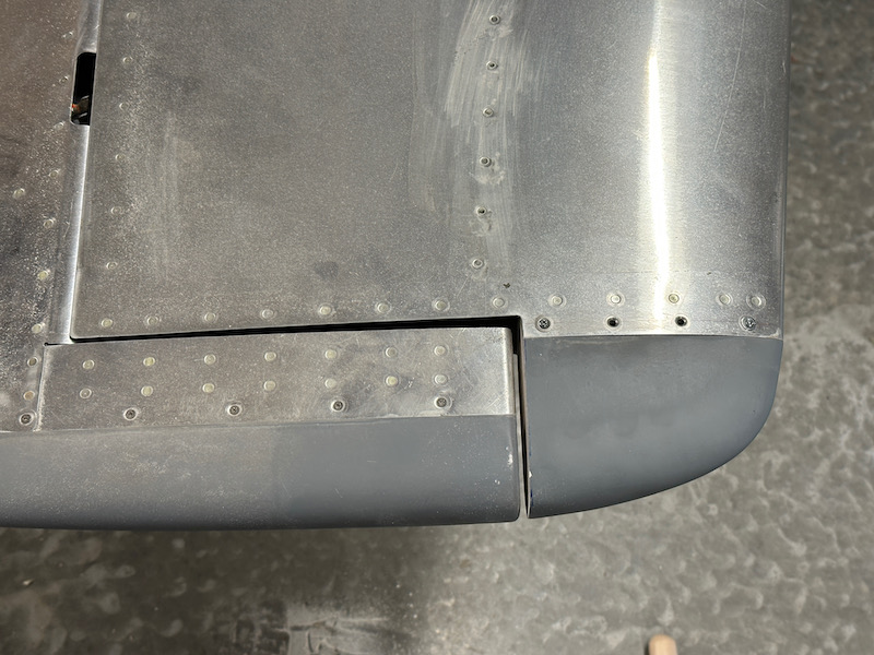
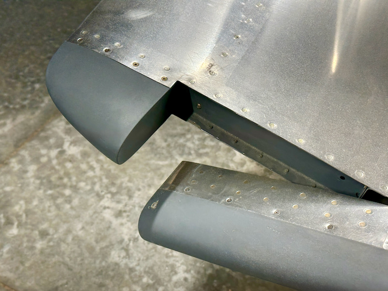
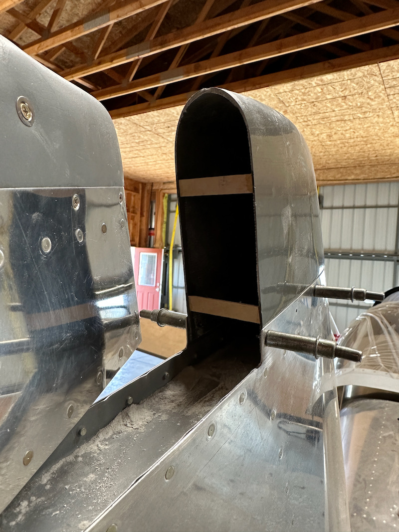
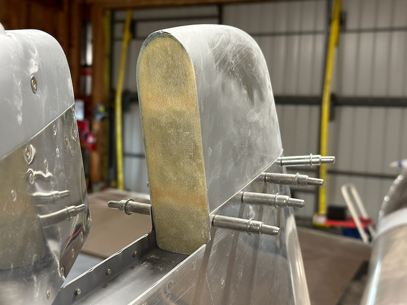
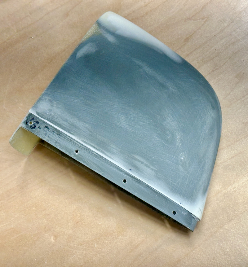
While working on the rudder fit and the vertical stabilizer fairing, I decided to re-check the clearance between the elevators and the horizontal stabilizer tip fairings. I was surprised to find that I had inadequate clearance (less than the minimum 1/8") on the starboard side. Not sure what happened there, perhaps I had the elevator hinge bearings adjusted differently during fitting versus how they are installed now.

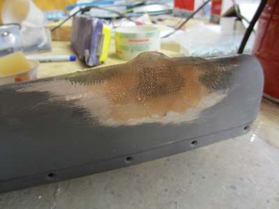
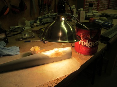
I sanded the fairing to fix the clearance issue, which resulted in me sanding right through the epoxy layer and into the balsa wood underneath. So something needed to be done about that:

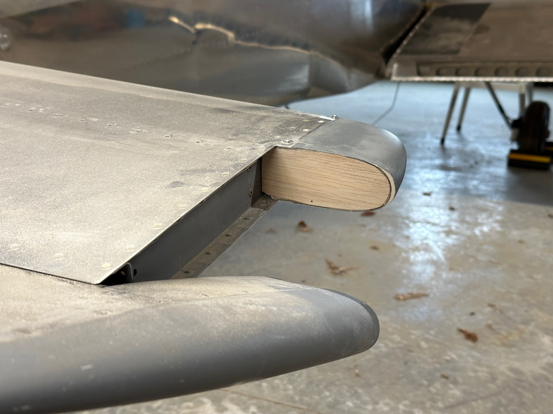
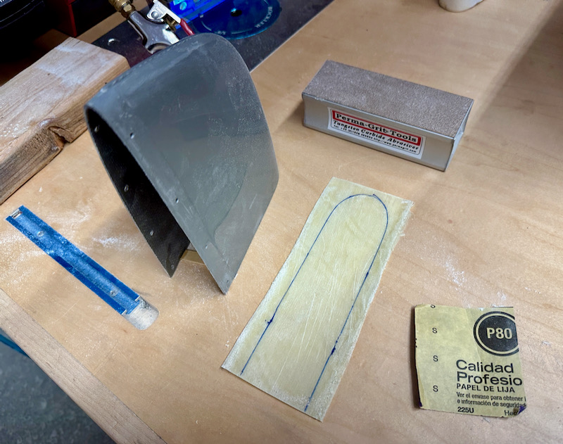
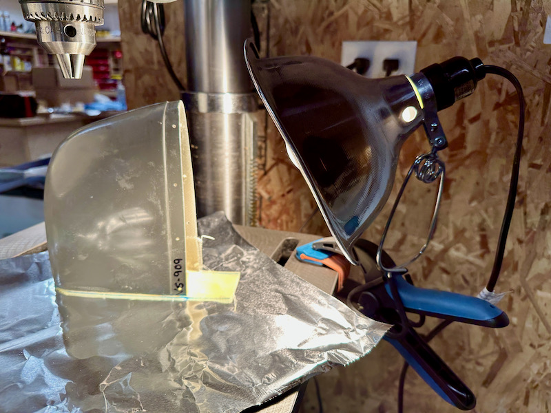
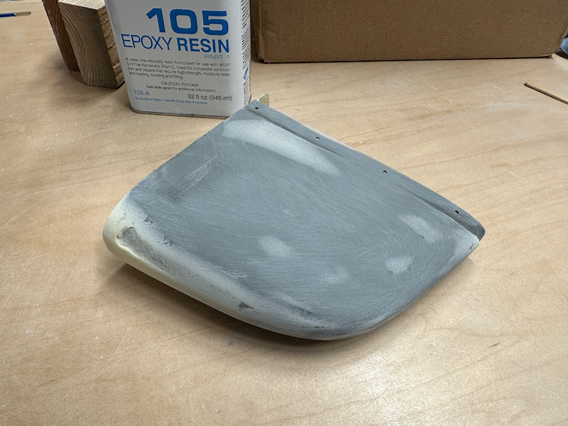
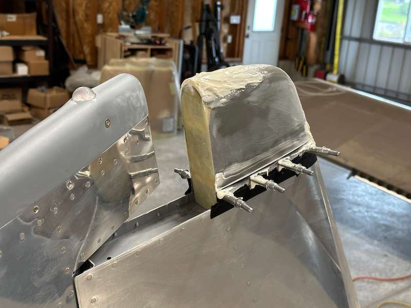
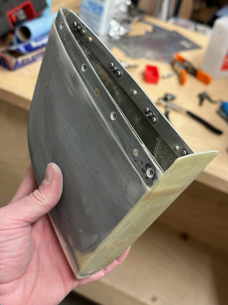
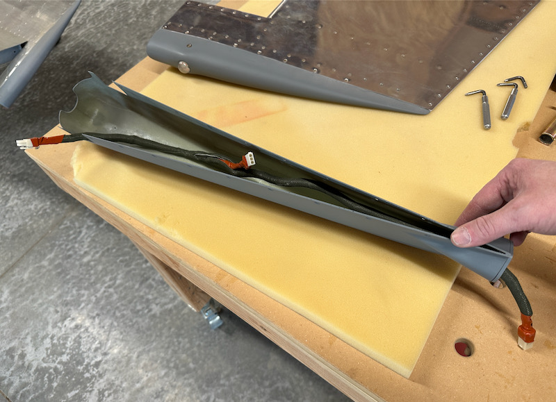
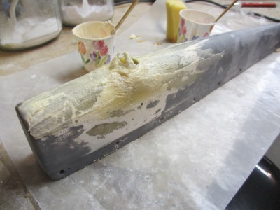
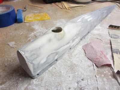
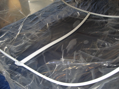
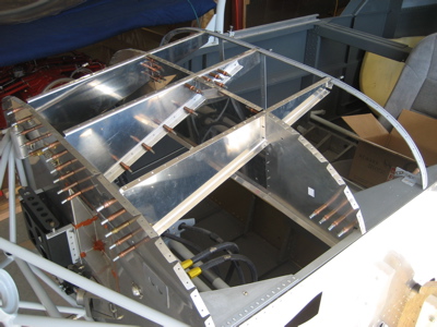
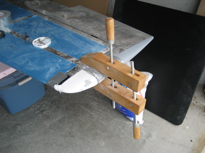
I had been regretting using balsa anyway, so I carved it all out and replaced it with fiberglass just like I did with the vertical stabilizer fairing. Of course I had to do both sides so they'd be identical, otherwise I wouldn't be able to sleep at night. The process here was identical to that used for the VS fairing: popsicle stick supports, glass panel bonded with flox bead, additional glass layer on the inside. I promise it turned out nice even though this in-progress picture makes it look terrible:

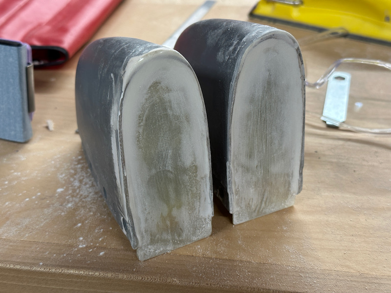
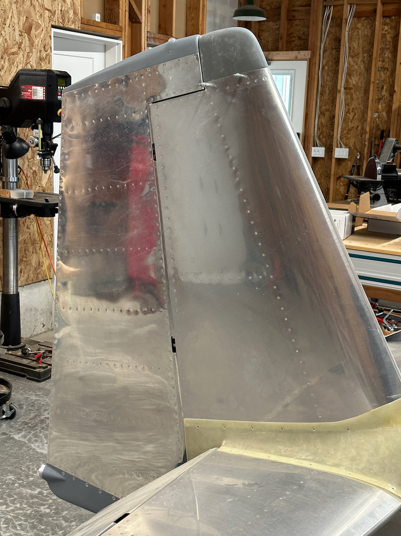
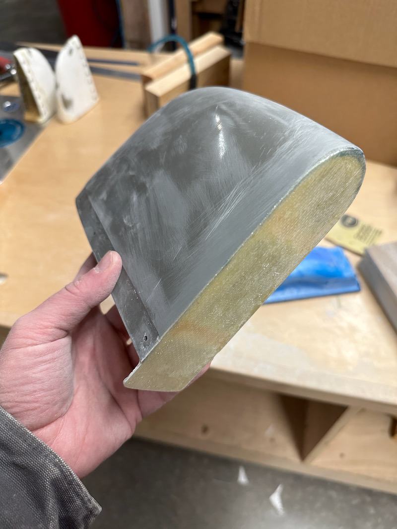
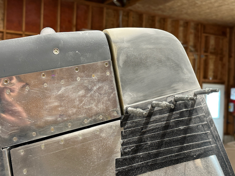
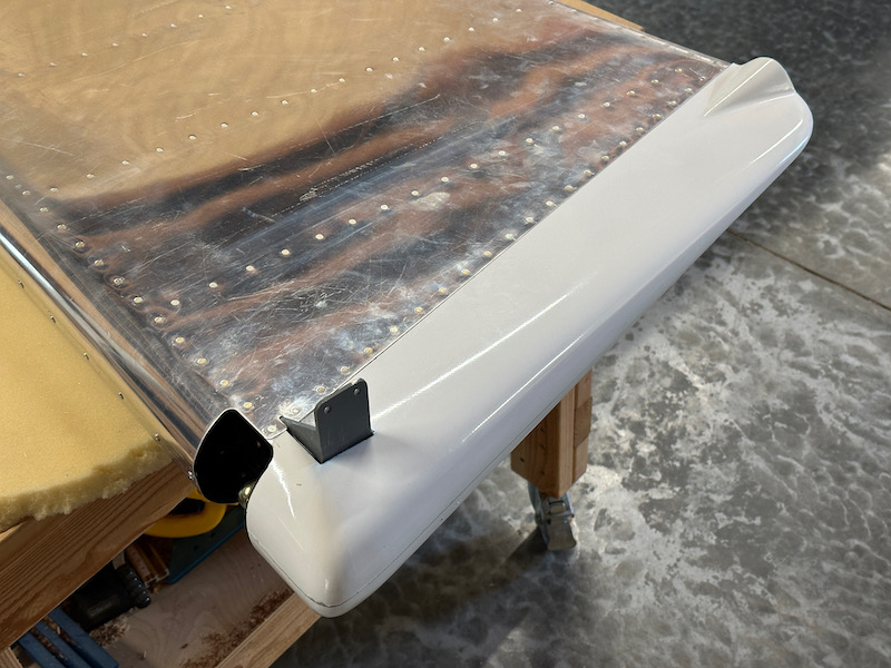
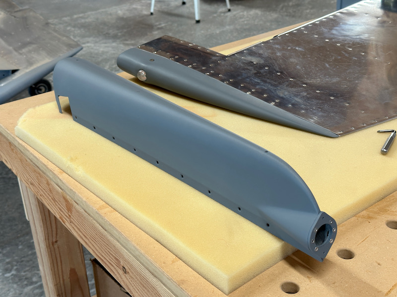
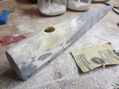
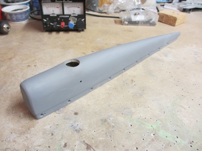
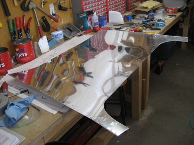
I sprayed all these fairings with several coats of SEM high-build primer, then sanded lightly with 320 grit. I like this stuff – it's expensive but it gives a decent result, and it comes in a handy spray can.

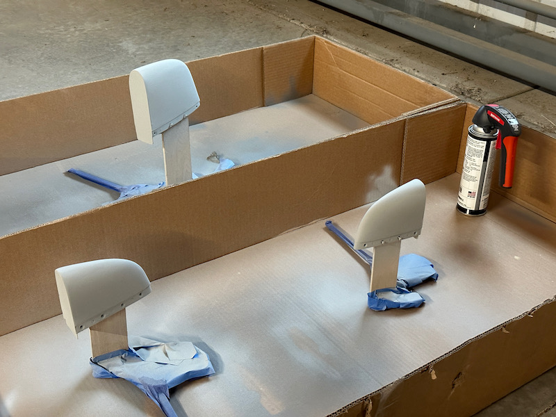
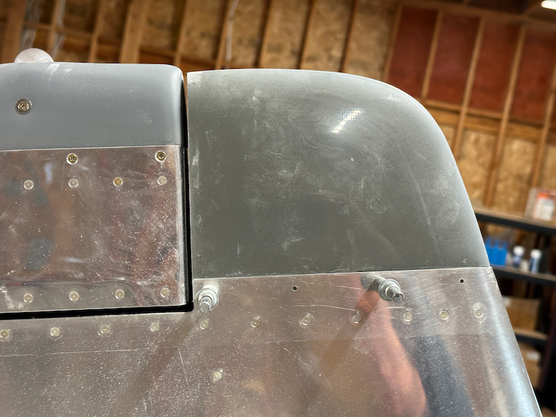
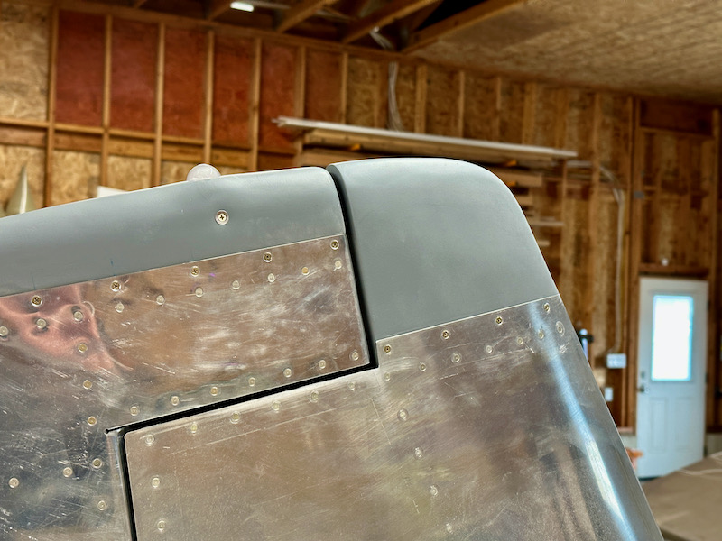
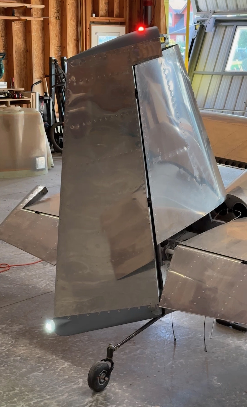
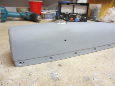
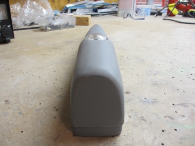
As before, I followed up with a cosmetic coat of 7220 and installed the fairings on the plane. And just as before, the results are not perfect but close enough that I'm happy for now. The pro painter will have a few pinholes to fill, but the shape is correct and the clearance problems are gone:

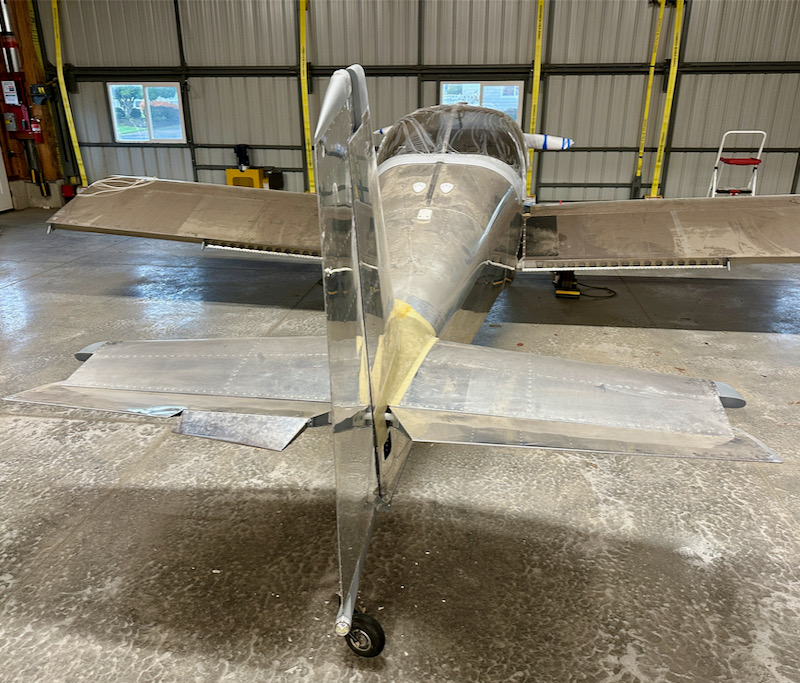
So now all the fairings on the tail of the airplane are technically done, although I still want to work on improving the fit of the empennage fairing. But that will have to wait for next year's fiberglass season – it's now too cold and rainy for that kind of work.

Vertical stabilizer fairing

Sunday, November 6th, 2022

With the rudder finished and installed on the airplane, I'm now able to fit the vertical stabilizer fairing. Here it is clecoed to the skin:

Unfortunately the shapes of the vertical stabilizer and rudder fairings don't match at all. Given that Van's can produce metal parts with holes that align perfectly, I'm not sure why their fiberglass parts are so troublesome – you'd think they'd be able to turn out properly-sized fairings in some kind of CNC-produced mold. But anyway, this mismatch needs to get fixed:

The back face of the fairing also needs to be closed up with something. I decided to use the method currently given in the RV-14 plans, and laid up three plies of glass over a flat piece of aluminum (visible at left). Oh fiberglass mess, how I have not missed you.

While that was curing, I cut some popsicle sticks to the correct size and super-glued them inside the fairing, flush with the edge. These will keep the fairing from collapsing when it's removed from the plane:

I ended up with a thin, flat sheet of stiff plastic, which I marked and trimmed slightly oversize:

Then I bonded it to the fairing with a flox bead, and an additional glass layer on the inside. The RV-14 plans tell you to do this step on the airplane, which seems like it would be messy; the popsicle sticks allow you to do this on the workbench where you can control the mess easier. I left it to cure overnight under an incandescent lamp due to the arrival of winter weather here in the northwest:

After curing I sanded the edges flush, and the result is pretty good. The popsicle sticks are now sandwiched between glass layers, which will prevent them from soaking up water and swelling:

The little tongue at the bottom took a few iterations to sand to the right shape:

Making the fairing structurally complete is easy enough – the hard part is making it look nice. I protected the vertical stabilizer with tape, stuck in a piece of vinyl-covered aluminum as a divider, and slathered on the first application of micro filler:

After sanding most of it off, the shape is starting to improve… note the built-up areas at the nose as well as on top:

Another round to fill the low spots:

Sanding flush with the skin:

Here's the finished result, which looks terrible visually but is now the correct shape and smoothed to 320 grit:

I did the usual thing with nutplates mounted on aluminum strips:

After a few coats of high-build primer, more sanding, and a final cosmetic coat of 7220, this is the finished result. Not perfect, but good enough for now. Eventually I'll have a pro painter take care of the last 10% and make it look really nice.

Rudder finishing

Sunday, October 16th, 2022

If you are building a taildragger, you want to wait to fit the bottom rudder fairing until you can test-fit the rudder to the fuselage to make sure the fairing is not rubbing on the tailwheel. I dug my untouched rudder bottom fairing out of storage and iteratively trimmed away at it until I had it fitting pretty well. I used a Norton cutting disc and a variety of Perma-Grit tools, which made it go fairly quickly:

The fit around the rudder horn is not completely perfect, but you need a little extra room in the cutout to get the fairing installed anyway, so I'm acceptably happy with it. I taped the fairing to the rudder and drilled the mounting holes, stepping up to #27 and countersinking for Tinnerman washers:

I added a connector to the wire bundle that emerges from the vertical stabilizer spar, and added a layer of snake skin to hopefully protect it from chafing as the rudder moves:

After fiddling with the wiring bundle, I went back and removed more material from the forward end of the bottom fairing, including a semicircular cutout to keep it from sawing its way through the cable bundle:

Rather than try to install nuts for the nav/strobe light inside the narrow confines of the fairing, I bought a mounting adapter which simply pop-rivets in place:

I somehow misplaced my old Whelen beacon light unit, so I had to order a new one. In the intervening years they have greatly reduced the thickness of these little lights, so I had to make a new mounting bracket out of stuff I had laying around. You can also just barely see the O-ring I added to hopefully keep rain from running down around the light and getting into the rudder:

The new beacon light also comes with a small LED driver as part of the cable assembly. I added a connector so I can remove the top fairing, and attached the LED driver to the rudder using an adel clamp and one of the nutplates I had fortuitously decided to install in the top rib tooling holes:

I did a very minor amount of surface work on the bottom fairing – I'll let the painter take care of the rest – and shot a coat of grey primer just to make it look nicer and to make it match the top fairing:

I made a little wiring harness that lives inside the bottom of the rudder, connecting the fuselage to the beacon light and the nav/strobe light. Although this shouldn't move around much, I used snake skin here too since unfinished fiberglass is very abrasive:

I installed both fairings and mounted the rudder on the airplane with the proper hardware, after struggling to avoid dropping any fasteners down into the bottom of the rudder. The final full-up test confirmed that all the lights are working, which was gratifying to see:

The nav/strobe light is a Whelen 550 unit, which fits great into an RV rudder. I attached it to the mounting plate with some stainless screws from the hardware store:

I got the rudder cables hooked up, with cotter pins installed, before I ran out of steam and out of weekend:

Red beacon

Sunday, October 28th, 2012

I've been planning to put some kind of red flashing ground-recognition beacon on the airplane all along, and this weekend I finally got around to making it happen. For years I've been pondering exactly what kind of beacon I need and where to mount it – see here and here for details of previous plans that didn't get completed, plus thoughts on red beacons in general. What ended up working in my favor is the fact that, while I was trying to figure out what to do, the state of the art in LED technology has advanced to the point where it now makes more sense to use LEDs rather than xenon strobes or halogen flashers for this application.

The particular unit I picked is the Vertex LED lighthead by Whelen. These guys are known in aviation circles for making certified strobes and nav lights, but they make lots of automotive products too. This one is designed to work as a warning light for a cop car or other emergency vehicle, but it happens to also be the perfect size for an airplane too. Here's a photo I grabbed from the internet since I forgot to take a "before" shot prior to getting started:

I played with various mounting positions until I decided which one I liked best – it turned out to be the top of the tail, just like on your grandpa's Cessna. Then I got out the rudder cap and started cutting away at it with a unibit and Dremel tool.

The light will be held in place by two little pieces of scrap angle that will attach to the inside of the rudder cap.

A view from the bottom side. The beacon heatsink just fits into the widest point of the rudder cap.

That has the added advantage of putting the beacon about halfway back from the leading edge of the vertical stabilizer – farther back than on a Cessna – where the light shining directly forward will be blocked instead of getting into the cockpit and annoying me by glaring off the instrument panel.

The circuit board inside the beacon is flush with the top of the rudder cap. Now we just need to do something about the exposed shoulders of the heatsink sticking out into the breeze.

I covered the beacon with saran wrap and then laid up several plies of glass tape over it in a smooth shape:

It's a little late in the season to be doing fiberglass work – i.e. the temperature is a bit low in the garage – but for small projects you can cheat and use a heat lamp to get the resin to cure in a reasonable amount of time.

After sanding the initial layup, I installed the beacon again and followed up with a flox/cabosil mixture to build up the contour and give me a nice sharp edge around the opening for the lens.

I also laid up some flox inside the rudder cap to give the body of the beacon a nice solid shoulder to sit on, as well as thickening up the inside of the lens opening to avoid having a knife edge there.

After letting that cure and sanding it back down, the general shape of the "bump" for the beacon was basically done.

I applied one more coat of dry micro with a squeegee to fill in the low spots, then sanded it smooth.

A quick spray of primer dressed it right up. I'm quite happy with how the shape turned out. There are some small surface imperfections but I'll let the painter deal with those.

The beacon lens is very low profile. I still need to countersink the mounting holes in the sides, but that can wait until I get back the drawer full of #4 tinnerman washers I loaned out.

Now that it's all sanded smooth and blended in, the slight swell for the beacon is hardly noticeable:

What's that, you say you want to see my new rudder-mounted ground recognition beacon in operation? Very well:

It's hard to properly capture with the camera, but trust me, this thing is plenty bright.

Canopy work aborted

Saturday, March 31st, 2007

After putting some protective tape over the end of the slider frame latch tube, I flipped the canopy over and laid the frame inside.

The goal is to get the frame aligned on the previously marked centerline, in the fore-aft location that results in the best fit along the center spine tube. Then you mark the location of the latch tube and drill a 5/8" hole. I got as far as marking the hole location, but the temperature didn't get up nearly as high as I thought it would, so I had to give up on drilling/trimming the canopy for another day. Bah.

In an effort to find something else to do, I dug up the subpanel pieces, dimpled the top rib flanges, and clecoed the whole works into the fuselage.

Then I deburred the forward top skin, which I hadn't yet bothered to do. I dimpled where I could reach along the edges, leaving the holes along the firewall undimpled for now – the cowling attach hinges still need to be match-drilled there, much further down the road. Then I packed up the skin and drove over to John's to use my DRDT to dimple the rest of the skin. Not a very efficient use of building time, but it felt like a good day to spend a couple hours driving.

Somewhere in there I did some more filler work on the left horizontal stabilizer tip fairing. I've had this clamp for at least ten years and I'm pretty sure this is the first time I've ever used it.

Also, I stopped at Lowe's and tried to buy a new belt sander, but they were out. Bah.